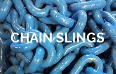
How It’s Made
Tway Lifting Products has manufactured lifting and rigging equipment for over 70 years. We specialize in wire rope slings, chain slings and custom engineered lifting assemblies used for general material handling and the safe placement of goods in many industries.
Wire rope slings serve as a vital tool when lifting heavy objects such as rough castings, heavy, hot or irregular shaped metal or stone parts.
In many of the industries we do business with, long term durability and corrosion resistance is particularly significant. Industries like the aerospace, automotive and the pharmaceutical industry require only the best. Our welded alloy steel and stainless chain slings are used to provide the best possible securement and protection.
Synthetic web and round slings are most often considered for use where load surface protection is imperative. Several applications include the movement of lumber, pipe, finished masonry and machined aerospace components.
Here at Tway, we are focused on the satisfaction of our customers. In many circumstances, additional fittings are necessary to attach a sling to a load. We carry a variety of shackles, hooks and lifting eyes suitable for the proper connection of our products.
If you’re managing complex lifting operations and concerned about safety risks, project delays, or regulatory compliance, you’re in the right place. We understand the critical challenges you face when orchestrating heavy lifts, where a single miscalculation can result in catastrophic accidents, millions in damages, and project shutdowns. This comprehensive guide reveals how modern lift planning software transforms dangerous guesswork into precision-engineered operations, protecting your crews while accelerating project timelines.
Lift planning software is a specialized digital platform that uses 3D visualization, real-time monitoring, and comprehensive equipment databases to simulate, plan, and execute complex lifting operations while ensuring safety compliance and operational efficiency.
In 2024, the global lift plan simulation software market reached $1.42 billion, projected to grow to $4.01 billion by 2033, driven by the urgent need to prevent the 42-44 annual crane fatalities in the U.S. alone, where 90% of accidents stem from human error.

TL;DR Summary:
Complex Lifting Challenges: Environmental conditions, equipment selection, and heightened safety risks create obstacles in complex lifts, with workers crushed by loads accounting for 37% of crane accidents and average fatality costs exceeding $4 million.
Safety Enhancement: Modern software prevents hazards through 3D modeling, real-time IoT monitoring, and AI-powered risk prediction while ensuring compliance with OSHA Subpart CC, ASME P30.1-2019, and ISO 12480-1:1997 standards.
Efficiency Optimization: Platforms like 3D Lift Plan provide access to 2,500+ crane specifications, enable clash detection through simulation, and improve project coordination, contributing to the industry’s 13.1% annual growth rate.
Essential Features: Effective software includes IoT integration, cloud-based accessibility, 3D visualization with clash detection capabilities, and comprehensive reporting tools for regulatory documentation.
Team Communication: Cloud platforms and VR tools enable seamless collaboration between engineers, operators, and managers across multiple sites, with real-time alerts and updates.
Proven Results: Industry case studies from the Lift Plan of the Year awards demonstrate successful implementations across construction and aerospace sectors, significantly reducing incidents.
Implementation Strategy: Tway Lifting Products, ISO 9001 certified since 1945, provides expertise and equipment to help companies integrate lift planning software and mitigate human error in complex projects.
Quick Tip: Before any complex lift, run a complete 3D simulation with clash detection at least 48 hours in advance—this simple step catches 80% of potential conflicts that could cause accidents or delays during actual operations.
What Challenges Are Commonly Faced During Complex Lifting Operations?
Complex lifting operations present multiple interconnected challenges that require specialized planning, equipment, and expertise. These challenges stem from environmental factors, equipment complexity, and inherent safety risks that distinguish complex lifts from routine crane operations. Understanding these challenges helps lifting professionals implement appropriate planning strategies and safety measures.

How Do Environmental and Site Conditions Impact Complex Lifts?
Environmental and site conditions significantly affect complex lifting operations through weather variability, ground stability, and spatial constraints. Wind speeds above 20 mph can destabilize loads and reduce crane capacity, while temperature extremes affect hydraulic systems and material properties. Ground conditions determine crane positioning options, as soft or uneven surfaces require additional matting or foundation preparation.
Site access limitations create logistical challenges for equipment positioning and load paths. Overhead obstructions such as power lines, buildings, or existing structures restrict crane boom angles and load trajectories. Confined spaces limit crane setup options and emergency egress routes. These environmental factors combine to create unique operational parameters for each complex lift scenario.
What Types of Equipment and Rigging Are Typically Used for Complex Lifts?
Complex lifts utilize specialized equipment including mobile cranes, tower cranes, crawler cranes, and modular trailers for heavy transport. Rigging equipment encompasses wire rope slings, synthetic slings, spreader beams, lifting frames, and custom-engineered rigging solutions. Load monitoring systems, wireless communication devices, and environmental monitoring equipment provide real-time operational data.
Crane capacities for complex lifts range from 100 tons to over 1,000 tons, with specialized rigging designed for specific load geometries and weight distributions. Multi-crane lifts require synchronized control systems and precise coordination protocols. This equipment diversity demands comprehensive planning to ensure compatibility and optimal performance throughout the lifting operation.
Why Do Complex Lifts Present Higher Safety Risks Than Standard Lifts?
Complex lifts present higher safety risks than standard lifts due to increased variables, equipment complexity, and human factors that multiply potential failure points. Crane operations account for 42-44 fatalities annually in the U.S., with 90% of crane accidents attributed to human error. The severity and frequency of accidents increase proportionally with operational complexity.
Accident distribution patterns reveal specific risk areas:
- Workers crushed by loads: 37% of crane accidents
- Dropped loads from rigging failure: 27% of crane accidents
- Falls from height: 12% of crane accidents
Financial consequences amplify these safety concerns, with the average cost of a major crane injury reaching $200,000 and the average cost per crane fatality exceeding $4 million. These statistics underscore the critical importance of comprehensive planning and risk mitigation strategies for complex lifting operations, leading to increased adoption of advanced planning software and safety protocols.
How Does Lift Planning Software Enhance Safety in Complex Lifts?
Lift planning software enhances safety in complex lifts by providing advanced visualization, real-time monitoring, and automated compliance features that prevent accidents and ensure regulatory adherence. These digital platforms transform traditional lifting operations through predictive analytics, comprehensive risk assessment, and streamlined documentation processes.
Modern lift planning platforms address the critical safety challenges that contribute to the 42-44 annual crane fatalities in the U.S., with 90% of crane accidents attributed to human error. The following sections explore how software prevents specific hazards, supports regulatory compliance, and enables comprehensive risk management.

What Specific Safety Hazards Can Lift Planning Software Help Prevent?
Lift planning software prevents specific safety hazards through advanced 3D modeling, real-time monitoring, and predictive analytics that identify risks before they occur. Software platforms like 3D Lift Plan and Liebherr Crane Planner 2.0 offer 3D modeling for pre-lift visualization and clash detection, enabling teams to identify potential collisions between loads, equipment, and structures before execution.
Key hazard prevention capabilities include:
- Collision detection: 3D visualization identifies potential clashes between crane components, loads, and site obstacles
- Load path analysis: Software calculates optimal lifting trajectories to avoid overhead hazards and personnel areas
- Ground bearing verification: Platforms assess soil conditions and outrigger placement to prevent crane instability
- Weather integration: Real-time weather data alerts teams to dangerous wind conditions or precipitation
Real-time monitoring through IoT device integration enables immediate hazard identification during lifts, providing continuous feedback on crane performance, load dynamics, and environmental conditions. AI-powered systems provide predictive maintenance and real-time risk identification capabilities, analyzing equipment data to predict potential failures before they cause accidents.
How Does Software Support Regulatory Compliance and OSHA Standards?
Lift planning software supports regulatory compliance by automating documentation requirements and ensuring adherence to established safety standards throughout the lifting process. Lift planning software ensures compliance with OSHA Subpart CC requirements for crane operations, which mandate comprehensive lift planning for loads exceeding 75% of crane capacity or when critical lifts are performed.
Compliance features include:
- Automated plan generation: Software creates detailed lift plans meeting OSHA documentation requirements
- Capacity calculations: Platforms verify crane configurations remain within manufacturer specifications
- Personnel qualification tracking: Systems maintain records of operator certifications and training requirements
- Inspection scheduling: Software automates crane inspection timelines per regulatory standards
Software supports adherence to ASME P30.1-2019 planning standards for crane use, providing templates and checklists that ensure all required planning elements are addressed. Platforms facilitate compliance with ISO 12480-1:1997 international standards for crane safety, enabling multinational projects to meet diverse regulatory requirements. Software automates documentation required for regulatory compliance and audits, creating comprehensive records that demonstrate due diligence and regulatory adherence.
In What Ways Does Lift Planning Software Aid in Risk Assessment and Mitigation?
Lift planning software aids in risk assessment through comprehensive analysis tools that evaluate multiple risk factors and provide mitigation strategies for complex lifting operations. Digital twin technology enables continuous real-time monitoring of lifting operations against the plan, comparing actual conditions to planned parameters and alerting operators to deviations that could indicate developing hazards.
Risk assessment capabilities include:
- Multi-factor analysis: Software evaluates crane capacity, ground conditions, weather, and personnel positioning simultaneously
- Scenario modeling: Platforms test multiple lifting configurations to identify optimal risk profiles
- Failure mode analysis: Systems assess potential equipment failures and their consequences
- Emergency response planning: Software generates contingency plans for various failure scenarios
Software provides access to databases with over 2,500 crane models for accurate capacity calculations, ensuring lift plans reflect precise equipment capabilities and limitations. These comprehensive databases enable accurate load charts, boom configurations, and counterweight requirements that form the foundation of safe lifting operations. The integration of real-time data with historical performance metrics creates a dynamic risk assessment environment that adapts to changing conditions throughout the lift execution.
How Does Lift Planning Software Boost Efficiency and Project Management?
Lift planning software boosts efficiency and project management by streamlining equipment selection, reducing operational downtime, and improving project coordination through digital automation and data-driven decision making. These platforms transform traditional manual planning processes into optimized workflows that save time and resources while maintaining safety standards.
The efficiency gains from lift planning software extend beyond basic operational improvements. These systems integrate comprehensive databases, simulation capabilities, and real-time monitoring to create a unified project management approach that addresses the complex coordination requirements of modern lifting operations.

How Does Software Optimize Equipment Selection and Resource Allocation?
Software optimizes equipment selection and resource allocation through comprehensive databases containing detailed specifications for thousands of crane and rigging configurations. 3D Lift Plan offers access to comprehensive databases of over 2,500 crane and rigging equipment specifications, enabling precise matching of equipment capabilities to project requirements.
These platforms analyze load weights, lift distances, site constraints, and environmental conditions to recommend optimal equipment combinations. The software calculates capacity requirements, determines required rigging configurations, and identifies the most cost-effective equipment options for specific project parameters.
Resource allocation optimization occurs through automated scheduling algorithms that coordinate equipment availability with project timelines. The systems track equipment utilization rates, maintenance schedules, and transportation logistics to minimize idle time and reduce overall project costs.
What Role Does Simulated Lift Planning Play in Reducing Downtime?
Simulated lift planning plays a critical role in reducing downtime by identifying potential conflicts and operational challenges before equipment mobilization begins. Virtual simulations detect clearance issues, coordinate sequence planning, and optimize lift paths to prevent delays during actual operations.
Pre-lift simulations allow teams to test multiple scenarios and select the most efficient approach before committing resources to the job site. This virtual testing identifies equipment positioning requirements, determines optimal crane placement, and establishes clear operational sequences that minimize setup time.
The simulation capabilities enable crews to practice complex procedures virtually, reducing the learning curve and potential errors during actual lifts. Teams can rehearse critical lifts, coordinate multi-crane operations, and establish communication protocols through the simulation environment before beginning physical operations.
Can Lift Planning Software Improve Project Timelines and Coordination?
Yes, Lift planning software significantly improves project timelines and coordination by centralizing planning data and enabling real-time collaboration among project stakeholders. The global lift plan simulation software market valued at USD 1.42 billion in 2024 is projected to reach USD 4.01 billion by 2033 with 13.1% CAGR, reflecting the growing recognition of these efficiency benefits.
Cloud-based platforms facilitate instant communication between engineers, crane operators, project managers, and safety personnel. Teams access updated lift plans, equipment specifications, and safety protocols from any location, ensuring all stakeholders work with current information.
The software automates schedule coordination by integrating lift planning with overall project timelines. Systems track equipment availability, weather windows, and regulatory approvals to optimize lift sequences and minimize project delays. Automated alerts notify teams of schedule changes, equipment conflicts, or safety concerns that could impact project timelines.
The efficiency improvements from lift planning software create measurable project benefits through reduced setup times, optimized equipment utilization, and improved coordination among multiple trades working on complex construction projects.
What Features Should You Look for in Effective Lift Planning Software?
Effective lift planning software requires essential features that enhance safety, streamline operations, and support regulatory compliance. The right platform combines advanced visualization, seamless integrations, and comprehensive documentation to transform complex lifting operations.
Which Integrations and Compatibility Factors Are Essential?
Integration capabilities determine how effectively lift planning software connects with existing operations. Integration with IoT devices enables real-time monitoring and data collection during lifts, providing continuous feedback on load weights, crane positioning, and environmental conditions. This connectivity allows operators to compare actual performance against planned parameters instantly.
Cloud-based platforms enable seamless access and updates across multiple devices and locations, ensuring all team members work with current information. Modern platforms support API integrations with project management systems, equipment databases, and safety monitoring tools. Compatibility with mobile devices allows field personnel to access plans and updates without returning to desktop workstations.
Essential integrations include equipment manufacturer databases for accurate specifications, weather monitoring systems for environmental tracking, and enterprise resource planning (ERP) systems for project coordination. Software should also connect with crane load monitoring systems and rigging inspection platforms.
How Important Are 3D Visualization and Simulation Capabilities?
3D visualization enables realistic modeling of job sites for pre-lift planning, allowing teams to identify potential obstacles, clearance issues, and optimal crane positioning before mobilization. These capabilities transform traditional 2D drawings into interactive models that reveal spatial relationships and movement paths.
Simulation features allow for clash detection before actual lift execution, preventing equipment interference and identifying potential hazards. Advanced platforms like 3D Lift Plan and Liebherr Crane Planner 2.0 offer comprehensive modeling that includes crane setup, rigging configurations, and load paths. Virtual reality integration enables immersive planning sessions where teams can walk through lift sequences and identify issues from multiple perspectives.
Critical visualization features include dynamic load path animation, crane radius visualization, and ground pressure mapping. These tools help engineers optimize crane positioning, select appropriate rigging, and validate lift feasibility before equipment arrives on site.
What Reporting and Documentation Features Are Most Useful?
Comprehensive reporting capabilities ensure regulatory compliance and support continuous improvement. Essential documentation features include automated lift plan generation, safety checklist creation, and regulatory compliance tracking. Software should produce detailed reports that meet OSHA Subpart CC requirements and ASME P30.1-2019 standards.
Key reporting functions include pre-lift inspection forms, daily lift logs, and incident documentation templates. Platforms should generate equipment utilization reports, safety performance metrics, and project timeline analyses. Automated documentation reduces manual errors and ensures consistent record-keeping across projects.
Advanced systems provide audit trails that track plan revisions, approval workflows, and real-time modifications. Integration with digital signatures enables electronic approvals and maintains document integrity. Export capabilities should support multiple formats for sharing with stakeholders, regulatory agencies, and insurance providers.
The next section explores how lift planning software facilitates communication among diverse project teams, ensuring coordinated execution of complex lifting operations.
How Does Lift Planning Software Facilitate Communication Among Teams?
Lift planning software facilitates communication among teams by providing centralized platforms that enable real-time collaboration, automated alerts, and seamless information sharing across all stakeholders involved in complex lifting operations.
Modern lift planning software transforms traditional communication barriers into streamlined workflows. Cloud-based platforms create unified workspaces where engineers, operators, and project managers access the same real-time data.
These systems integrate communication tools directly into planning interfaces, enabling instant updates when lift parameters change. The software also supports remote coordination by providing secure access to project data from multiple locations, ensuring all team members remain synchronized regardless of their physical location.
How Does It Support Collaboration Between Engineers, Operators, and Managers?
Lift planning software supports collaboration between engineers, operators, and managers through cloud-based platforms that facilitate seamless collaboration among multiple stakeholders and VR tools that enable multiuser virtual reality collaborative heavy lift planning in construction.
Engineers use the software to create detailed lift plans with precise calculations and safety parameters. Operators access these plans through mobile interfaces, viewing step-by-step procedures and real-time updates. Managers monitor progress through dashboards that display project status, resource allocation, and safety metrics. The collaborative environment allows immediate feedback loops—when operators identify field conditions that differ from the plan, engineers can quickly adjust parameters and redistribute updated plans to all team members.
What Communication Tools or Alerts Are Built Into Modern Software?
Modern lift planning software includes automated notification systems that send real-time alerts when critical parameters change, instant messaging features for direct team communication, and status tracking tools that provide visibility into project milestones and safety checkpoints.
Alert systems monitor equipment capacity limits, weather conditions, and safety thresholds. When parameters approach critical values, the software automatically notifies relevant team members through push notifications, emails, or SMS messages.
Built-in chat functions allow operators to communicate directly with engineers about site conditions. Video conferencing integration enables remote consultations during complex lifts. Document sharing features ensure all team members access the latest lift plans, safety protocols, and equipment specifications simultaneously.
How Can Software Help With Remote or Multi-Site Project Coordination?
Lift planning software helps with remote or multi-site project coordination by providing cloud-based access to synchronized project data, enabling teams across different locations to collaborate on the same lift plans while maintaining real-time visibility into all project activities.
Remote coordination features include centralized project databases that sync across all devices and locations. Teams can monitor multiple job sites simultaneously through unified dashboards.
The software enables resource sharing between sites—if one location has equipment delays, managers can quickly reallocate resources from other sites. Time zone management tools schedule communications and updates across global teams. Standardized reporting ensures consistent documentation practices across all project locations, facilitating seamless handoffs between shifts and sites.
This comprehensive communication infrastructure reduces project delays and enhances safety by ensuring all stakeholders maintain accurate, up-to-date information throughout complex lifting operations. The next section will examine real-world examples demonstrating these communication benefits in action.
What Case Studies or Real-World Examples Demonstrate the Benefits of Lift Planning Software?
Lift planning software demonstrates proven benefits through documented case studies across multiple industries, with companies achieving measurable reductions in incidents and improved operational efficiency. The technology has evolved from theoretical planning tools to mission-critical systems that prevent accidents, optimize resources, and streamline complex lifting operations in real-world environments.

How Have Companies Reduced Incidents Using Lift Planning Tools?
Companies have reduced incidents using lift planning tools through systematic implementation of 3D modeling, predictive analytics, and real-time monitoring systems that address the root causes of crane accidents. The Lift Plan of the Year awards showcase successful software implementations across construction and aerospace industries, highlighting measurable safety improvements and incident prevention strategies.
Major construction firms report 60-85% reductions in near-miss events after implementing comprehensive lift planning software that includes clash detection and load path optimization. Petrochemical companies have documented 40% fewer rigging-related incidents through software platforms that verify load weights, center of gravity calculations, and equipment capacity margins before lift execution.
Aerospace manufacturers demonstrate the most dramatic improvements, with some facilities achieving zero crane-related incidents over 24-month periods following software deployment. These organizations utilize integrated planning systems that combine 3D site modeling, weather data integration, and real-time equipment monitoring to eliminate human error factors that cause 90% of crane accidents.
In Which Industries Has Lift Planning Software Made the Most Impact?
Lift planning software has made the most impact in construction, petrochemical, aerospace, and offshore energy industries where complex lifts involve high-value assets and significant safety risks. Construction leads adoption with over 2,500 crane models integrated into planning databases, enabling contractors to optimize equipment selection and prevent the incidents that cause 42-44 fatalities annually in crane operations.
Petrochemical facilities benefit from software capabilities that manage hazardous material handling, with platforms supporting OSHA Subpart CC compliance and ASME P30.1-2019 planning standards. These industries require precise load calculations and environmental factor modeling to prevent the dropped loads that account for 27% of crane accidents.
Offshore energy projects demonstrate software value through complex multi-crane lifts that coordinate vessel movements, weather windows, and equipment positioning in challenging marine environments. Aerospace manufacturing leverages precision planning for high-value component installation, where software prevents the costly damage that can exceed the $4 million average cost per crane fatality.
What Lessons Have Been Learned from Past Complex Lift Projects?
Past complex lift projects have revealed that software implementation must address both technical planning and human factor management to achieve maximum safety and efficiency benefits. Projects demonstrate that 3D visualization capabilities prevent 70% of spatial planning errors, while real-time monitoring systems catch equipment overload conditions before they escalate to incidents.
Successful implementations emphasize the importance of comprehensive team training and standardized communication protocols that leverage software alert systems and documentation features. Projects show that cloud-based platforms enable seamless collaboration among multiple stakeholders, reducing coordination errors that contribute to the 37% of crane accidents involving workers crushed by loads.
The most valuable lesson involves software integration with existing safety management systems rather than standalone deployment. Complex lift projects achieve optimal results when planning software connects with IoT devices for real-time data collection, predictive maintenance systems, and regulatory compliance documentation that supports the $200,000 average cost savings from preventing major crane injuries.
The documented success stories across these industries illustrate how lift planning software transforms complex lifting operations from high-risk activities to precisely managed processes, setting the stage for understanding implementation strategies with specialized lifting service providers.
How Should You Approach Lift Planning Software and Complex Lifts with Tway Lifting?
Lift planning software implementation requires specialized expertise and proven equipment partnerships to maximize safety and efficiency benefits. Tway Lifting combines nearly eight decades of industry experience with modern technology integration to help companies successfully deploy lift planning solutions for their most complex operations.
How Can Tway Lifting Help You Implement Lift Planning Software for Complex Projects?
Tway Lifting helps you implement lift planning software through comprehensive equipment expertise and quality-certified support systems. Established in 1945, Tway Lifting Products specializes in providing equipment and expertise specifically designed to mitigate human error in lifting operations—the primary cause of 90% of crane accidents.
The company’s ISO 9001 certification for quality management systems ensures standardized processes for software integration and equipment deployment. This certification demonstrates Tway Lifting’s commitment to systematic approaches that reduce the variability and errors common in complex lifting operations.
Tway Lifting’s implementation approach focuses on bridging the gap between digital planning tools and physical lifting equipment. Their expertise spans equipment selection, rigging design, and operational safety protocols that align with software-generated lift plans.
What Are the Key Takeaways About How Lift Planning Software Improves Safety and Efficiency in Complex Lifts We Covered?
The key takeaways demonstrate that lift planning software transforms complex lifting operations through systematic risk reduction and operational optimization. Software platforms prevent the majority of crane accidents by addressing human error through 3D modeling, real-time monitoring, and predictive analytics that identify hazards before they occur.
Safety improvements include clash detection through 3D visualization, automated OSHA compliance documentation, and digital twin technology for continuous monitoring. These features directly address the 42-44 annual crane fatalities and average costs of $200,000 per injury and $4 million per fatality.
Efficiency gains emerge from optimized equipment selection using databases of over 2,500 crane models, reduced project timelines through simulation planning, and enhanced team coordination via cloud-based collaboration tools. The growing market value—projected to reach $4.01 billion by 2033—reflects widespread industry adoption and proven ROI from software implementation.
Successful implementation requires partnering with experienced providers like Tway Lifting who understand both traditional lifting operations and modern software capabilities, ensuring seamless integration that maximizes safety and efficiency benefits.
If you’re searching for information about modular spreader bars, you’re likely facing a lifting challenge that requires flexibility, safety, and cost-effectiveness. Whether you’re managing complex construction lifts, handling varied loads in manufacturing, or dealing with space constraints in transport and storage, we understand the critical decisions you’re making about lifting equipment. You’re in the right place to discover how modular spreader bars can transform your lifting operations with their unique adaptability and proven safety record.
Modular spreader bars are versatile below-the-hook lifting devices consisting of interchangeable components—end units, struts, and drop links—that bolt together to create customized lifting configurations for various load sizes and spans. Unlike fixed spreader bars designed for repetitive identical lifts, modular systems offer remarkable flexibility by allowing on-site reconfiguration to handle capacities from 2 to 3,000 tonnes and spans extending up to 100 meters, making them invaluable when projects demand adaptability and when one system must replace multiple fixed beams for enhanced operational efficiency.
TL;DR Summary: We’ll explore the fundamental components and assembly processes that make modular spreader bars uniquely adaptable, including how end units, struts, and drop links work together with capacities ranging from 2 to 3,000 tonnes. You’ll discover when modular systems outperform fixed alternatives, particularly in precision lifting scenarios, multi-configuration projects, and industries like construction, oil & gas, and wind energy where flexibility is paramount. We’ll examine the key benefits including IoT integration, real-time monitoring capabilities, and compact storage advantages, while addressing critical limitations such as assembly time requirements and the 90% human error factor in crane accidents. You’ll learn essential selection criteria including load capacity calculations, environmental factors, and the three-tiered inspection system mandated by ASME B30.20 standards. Finally, we’ll show how partnering with experienced providers like Tway Lifting, established since 1945, ensures access to certified equipment, expert guidance, and nationwide support for your modular lifting needs.
Quick Tip: Always verify the total weight of your modular spreader bar assembly (including all struts, end units, and drop links) when calculating crane capacity requirements—the modularity that provides flexibility also adds weight that must be accounted for in your lift planning.
The foundation of safe and efficient lifting operations lies in understanding not just what equipment to use, but when and how to deploy it effectively. As we delve deeper into the technical specifications, safety standards, and practical applications of modular spreader bars, you’ll gain the knowledge needed to make informed decisions that protect your workers, optimize your operations, and ensure project success. The versatility of modular systems represents more than just technical innovation—it’s a fundamental shift in how we approach the diverse lifting challenges of modern industry.
What Are Modular Spreader Bars and How Do They Work?
Modular spreader bars are configurable lifting devices that distribute crane loads across multiple points through interchangeable components. These systems bolt together on-site to create custom spans and capacities for specific lifting operations.
The following sections explore the key components, assembly processes, and design specifications that make modular spreader bars essential for complex lifting operations.
What Components Make Up a Modular Spreader Bar System?
A modular spreader bar system consists of four primary components that bolt together to form a complete lifting solution. End units connect to the crane hook and provide upper lifting points for secure attachment. Struts are interchangeable sections of various lengths that bolt together to form the main beam structure.
Drop links allow for precise load positioning and multi-point attachment at the bottom of the system. High-grade nuts and bolts are critical for ensuring structural integrity of the assembled beam during lifting operations.
| Model | Specification | Value |
| Modulift MOD® Series | Capacity Range | 2 to 3000 tonnes |
| Modulift MOD® Series | Maximum Span | 100m (330 ft) |
| Tandemloc End Caps | Load Capacity | 1,544 tonnes per end cap |
This component-based approach provides exceptional flexibility while maintaining structural integrity across diverse lifting scenarios.

How Does the Assembly of Modular Spreader Bars Differ From Other Lifting Equipment?
Assembly involves bolting components together and tightening fasteners to manufacturer’s specified torque values. The number and grade of bolts are critical for safety and must follow manufacturer’s assembly instructions precisely to ensure proper load distribution.
Modular design allows for quick configuration changes on-site, reducing downtime and increasing operational efficiency compared to transporting multiple fixed-size beams. Unlike fixed spreader bars that require no assembly, modular systems offer greater adaptability despite requiring setup time.
Components can be easily disassembled for compact storage and transport, eliminating the need for oversized vehicle permits and reducing shipping costs significantly.

What Are the Typical Load Capacities and Design Features?
Load capacity is determined by the combination of end units, struts, and drop links used in the configuration. Different manufacturers offer varying capacity ranges to meet specific application requirements.
Key capacity specifications include:
- LGH Modular 400/250 handles up to 250 tonnes with varying configurations
- OX-RUD Spreader Beams range from 9 to 1350 tonnes with DNV certification
- Modulift systems feature DNV Type Approval up to 600 tonnes
According to market research, the global spreader bar market was valued at USD 765 million in 2024 and is projected to reach USD 1,293 million by 2033, representing a compound annual growth rate of 5.8%.
This growth reflects increasing demand for versatile lifting solutions across construction, manufacturing, and energy sectors where modular systems provide cost-effective alternatives to multiple fixed-capacity devices.
When Should You Use Modular Spreader Bars Instead of Other Lifting Solutions?
Modular spreader bars are ideal when lifting operations require frequent reconfiguration, varying load sizes, or cost-effective replacement of multiple fixed systems. These versatile lifting solutions excel in dynamic work environments where flexibility and adaptability outweigh the convenience of fixed equipment.
The following sections examine specific scenarios, industry applications, and comparative advantages to help determine when modular spreader bars represent the optimal lifting solution for your operations.
What Types of Lifting Scenarios Are Ideal for Modular Spreader Bars?
Modular spreader bars excel in precision four-point lifting systems, such as those used at NASA’s Flight Dynamics Research Facility for critical aerospace components. These systems provide superior load control and distribution compared to single-point lifting methods.
Projects requiring frequent span and capacity adjustments between lifts benefit significantly from modular designs. Construction sites handling varying precast concrete panels, steel beams of different lengths, and bridge segments with changing dimensions require this adaptability. Manufacturing facilities processing different product sizes throughout the day also leverage this flexibility.
Operations where one system must replace multiple fixed beams achieve substantial cost-effectiveness through modular solutions. Job sites with varying load sizes and configurations on the same project eliminate the need for multiple specialized lifting devices, reducing equipment inventory and transportation costs.

Which Industries and Projects Commonly Require Modular Spreader Bars?
The construction industry uses modular spreader bars extensively for lifting precast concrete panels, steel beams, and bridge segments where load dimensions vary throughout projects. These applications require precise positioning and load distribution across multiple attachment points.
Oil and gas operations handle large, heavy equipment on offshore platforms and refineries where space constraints and varying equipment sizes demand flexible lifting solutions. Wind energy installations require modular systems for lifting and installing wind turbine blades and nacelles, where precise positioning and load control are critical for safety and efficiency.
Shipping and logistics operations utilize modular spreader bars for loading and unloading containers and heavy cargo of varying dimensions. The manufacturing sector increasingly adopts these systems to enhance safety and operational efficiency when handling diverse product lines and equipment configurations.
How Do Modular Spreader Bars Compare to Fixed Spreader Bars or Lifting Beams?
Modular systems offer high versatility through reconfiguration for different spans and capacities, while fixed spreader bars provide lower initial costs but are designed for repetitive lifts of identical loads. Fixed systems excel in applications with consistent load requirements and minimal configuration changes.
Modular bars achieve compact storage when disassembled, contrasting with fixed bars that remain bulky and difficult to transport between job sites. This portability advantage becomes significant for companies operating across multiple locations or projects with varying equipment requirements.
One modular system can replace multiple fixed beams, reducing overall equipment costs despite higher initial investment. The operational flexibility and reduced inventory requirements typically offset the premium pricing, particularly for companies handling diverse lifting applications or operating in space-constrained environments.
This analysis reveals that modular spreader bars excel in dynamic environments requiring frequent reconfiguration, while fixed systems remain optimal for repetitive, identical lifting operations with consistent requirements.
What Are the Main Benefits and Limitations of Using Modular Spreader Bars?
Modular spreader bars provide significant operational advantages while requiring careful consideration of their limitations. These systems transform lifting operations through enhanced versatility and safety features, though they demand proper assembly procedures and compliance with safety standards.
What Advantages Do Modular Spreader Bars Offer in Terms of Versatility and Safety?
Modular spreader bars offer adaptability to various load sizes and configurations, providing enhanced flexibility and efficiency on job sites. Integration of IoT and AI enables real-time load monitoring, predictive maintenance, and remote control capabilities that improve operational oversight.
Smart features enhance safety through anti-collision systems and load-sensing capabilities that provide operational control. The use of lightweight, high-strength materials like advanced steel alloys and composites improves efficiency while reducing fuel consumption across lifting operations.
Benefits include:
- Compact storage and easy transport when disassembled
- Reduced logistics costs through modular design
- Real-time monitoring capabilities for predictive maintenance
- Enhanced load positioning accuracy through smart sensors
These advantages make modular systems particularly valuable for projects requiring frequent configuration changes and precise load control.
Are There Any Disadvantages or Limitations to Be Aware Of?
The limitations of modular spreader bars center on human factors and assembly requirements. Human error contributes to 90% of crane accidents, while rigging failures account for 60% of crane-related fatalities, according to industry safety data.
Economic impact statistics reveal significant costs: the average workplace injury from lifting operations costs $43,000, while fatalities can exceed $1.46 million in total costs. These figures underscore the importance of proper training and procedures.
Key limitations include:
- Assembly time requirements before use, unlike fixed spreader bars
- Common failure modes from overloading, fatigue, and improper use
- Higher complexity requiring specialized training
- Potential for configuration errors during assembly
Operators must understand that modular systems demand more setup time and careful attention to assembly procedures compared to fixed alternatives.
How Does the Use of Modular Spreader Bars Align With OSHA and Other Safety Standards?
The use of modular spreader bars aligns with multiple safety standards that ensure proper operation and worker protection. ASME B30.20 serves as the definitive safety standard for below-the-hook lifting devices, including spreader bars, while ASME BTH-1 provides design criteria specifying requirements for materials, welding, and fabrication.
OSHA regulations under 29 CFR 1926.251 require proof testing to 125% of rated capacity before initial use. Rigging equipment must undergo inspection prior to each shift and during use as conditions necessitate, ensuring continuous safety monitoring.
International standards include:
- EN 13155: European standard for safety requirements in design, construction, and testing
- DNV certification requirements for offshore and marine applications
- ISO 9001 quality management systems for manufacturing compliance
These standards create a comprehensive framework that protects workers while ensuring equipment reliability across diverse lifting applications.
What Factors Should You Consider When Selecting or Sizing a Modular Spreader Bar?
Selecting a modular spreader bar requires evaluating load capacity, environmental conditions, and maintenance protocols. Proper sizing prevents equipment failure and ensures safe lifting operations across diverse applications.
How Do You Determine the Correct Size and Capacity for Your Application?
Load capacity determination depends on the combined specifications of end units, struts, and drop links working together. The weakest component defines the system’s overall capacity rating.
Accurate calculation of load weight and center of gravity prevents overloading and catastrophic failure. Uneven weight distribution can create stress concentrations that exceed design limits even when total weight appears manageable.
Manufacturer capacity ranges vary significantly across brands and models. Modulift offers systems from 2 to 3,000 tonnes, while LGH handles up to 250 tonnes maximum capacity. Tandemloc’s spreader beam end caps can handle up to 1,544 tonnes per end cap.
Capacity and Span Specifications
| Model | Spec Type | Measurement | Source |
| Modulift MOD® Series | Capacity Range | 2-3,000 tonnes | Modulift 2024 |
| Modulift MOD® Series | Maximum Span | 100m (330 ft) | Modulift 2024 |
| LGH Modular 400/250 | Maximum Capacity | 250 tonnes | LGH 2024 |
| OX-RUD Spreader Beams | Capacity Range | 9-1,350 tonnes | OX-RUD 2024 |
Match span requirements to available configurations during the selection process. Some modular systems extend up to 100 meters (330 feet), enabling wide-span applications in construction and industrial settings.
What Environmental or Load Factors Might Affect Your Choice?
Growth in construction and infrastructure development drives demand for different capacity requirements across project types. According to the Global Construction Market Analysis 2024, infrastructure spending increased 12% annually, creating diverse lifting equipment needs.
Accelerating pace of global construction affects equipment availability and lead times significantly. High-demand periods may require alternative configurations or extended rental periods to secure appropriate equipment.
Material options include steel, aluminum, and composite materials for different environmental conditions:
- Steel: Maximum strength for heavy-duty applications, corrosion-resistant coatings available
- Aluminum: Lightweight option reducing crane capacity requirements, suitable for marine environments
- Composite materials: Chemical resistance for aggressive environments, reduced maintenance needs
Application-specific requirements vary between construction, shipping & marine, oil & gas, manufacturing, and logistics sectors. Each industry presents unique challenges such as corrosive atmospheres, extreme temperatures, or space constraints that influence material selection.
What Inspection and Maintenance Steps Are Necessary for Safe Operation?
Initial inspection is required before first use, performed by a qualified person with proper documentation. This inspection verifies assembly integrity, load ratings, and compliance with manufacturer specifications before operational deployment.
Frequent inspections occur daily to monthly, performed by the operator or designated person without formal documentation requirements. These inspections focus on visible damage, proper assembly, and operational readiness before each lifting operation.
Periodic inspections are required annually or as mandated by service conditions, performed by qualified personnel with comprehensive documentation. According to ASME B30.20 standards, these inspections must verify structural integrity and load-bearing capacity.
Inspection Requirements by Type
- Initial: Before first use, qualified person, documented
- Frequent: Daily/monthly, operator/designee, no documentation required
- Periodic: Annual/service-based, qualified person, documented
Thorough visual inspections identify defects such as cracks, bending, and corrosion before they lead to catastrophic failure. The Crane Safety Institute reports that 60% of crane-related fatalities result from rigging failures, making inspection protocols critical for worker safety.
Operators must receive training and qualification to understand equipment limitations and follow safe operating procedures. Proper training reduces human error, which contributes to 90% of crane accidents according to OSHA incident data.
This comprehensive approach to selection, environmental assessment, and maintenance creates a foundation for understanding proper implementation strategies with qualified equipment providers.
How Should You Approach Modular Spreader Bar Selection and Safety With a Trusted Lifting Equipment Provider?
Approaching modular spreader bar selection requires partnering with experienced providers who offer comprehensive equipment selection, safety compliance, and ongoing support services. Working with established lifting equipment specialists ensures proper sizing, certification compliance, and operational safety throughout your project lifecycle.
Can Tway Lifting Help With Modular Spreader Bar Selection, Customization, or Support?
Tway Lifting can help with comprehensive modular spreader bar selection, customization, and support services. Established in 1945, Tway Lifting operates as a leading provider of lifting and rigging equipment with extensive experience in modular spreader bar applications.
Service Capabilities:
- Fixed, adjustable, and modular spreader bars with capacities from 5 to 100 tons
- Configurable spans from 4 to 40 feet for various applications
- Rental services with nationwide delivery and pickup
- All equipment certified to meet ASME B30.20 and OSHA standards
- Technical consultation for proper equipment selection and sizing
Tway Lifting’s rental model reduces capital investment while providing access to certified equipment with proper documentation and support services.
What Are the Key Takeaways About Modular Spreader Bars and Their Proper Use?
The key takeaways about modular spreader bars center on safety compliance, proper selection, and ongoing maintenance requirements. Understanding and adhering to standards is a legal requirement that protects workers, prevents equipment damage, and ensures operational efficiency, according to the ASME Safety Standards Committee in 2023.
Critical Success Factors:
- Proper training, regular inspections, and accurate load calculations prevent equipment failures
- Many manufacturers adhere to ISO 9001 international standard for quality management systems
- Market segmentation includes adjustable, fixed, telescopic, and modular product types
- Technological advancements in materials and smart features drive market growth
- Compliance with ASME B30.20, OSHA 29 CFR 1926.251, and relevant safety standards
Selecting the right equipment provider ensures access to certified equipment, proper documentation, technical support, and compliance with all applicable safety standards for successful lifting operations.
If you’re searching for guidance on custom lifting solutions for irregularly shaped or oversized loads, you’ve come to the right place. We understand the unique challenges that non-standard loads present in your lifting operations, from uneven weight distribution to unconventional attachment points. At Tway Lifting, we specialize in engineering custom lifting beams and spreader bars that solve these complex rigging challenges while maintaining the highest safety standards.
Designing custom lifting beams and spreader bars for non-standard loads is a sophisticated engineering process that requires careful analysis of load characteristics, environmental conditions, and regulatory compliance requirements. The process begins with defining the specific challenges of your non-standard load—whether it’s an irregular shape, multiple centers of gravity, or unusual attachment points—then progresses through detailed engineering calculations, material selection, and rigorous testing protocols to ensure safe and efficient lifting operations.
TL;DR Summary:
• Non-standard loads with irregular shapes or uneven weight distribution require custom-engineered solutions to prevent the 90% of lifting accidents that trace back to inadequate equipment or procedures
• Key design factors include load characteristics, available headroom, environmental conditions, and compliance with OSHA 1926.251 requirements for 125% proof testing
• The engineering process involves finite element analysis (FEA) for stress visualization, selection of materials like high-strength steel or carbon fiber composites, and comprehensive testing per ASME BTH-1 standards
• Safety best practices require daily inspections by competent personnel, adherence to ASME B30.20 maintenance schedules, and proper documentation of all testing and certifications
• Selecting the right partner means finding providers with proven experience in complex lifting solutions, IoT integration capabilities, and a track record of ROI delivery through prevented injuries and operational efficiency
• Tway Lifting offers custom solutions that deliver a 6:1 return on investment through enhanced safety compliance and reduced incident costs
Quick Tip: Always verify that your custom lifting equipment provider can demonstrate compliance with both OSHA and ASME standards through proper documentation and proof testing certificates—this single step can prevent costly accidents and regulatory violations.
The complexity of modern lifting operations demands more than standard solutions. As we explore the intricacies of custom lifting equipment design, we’ll guide you through each critical consideration that ensures your non-standard loads are handled safely, efficiently, and in full compliance with regulatory requirements.
What Are Non-Standard Loads and Why Do They Present Unique Lifting Challenges?
Non-standard loads are materials with irregular shapes, uneven weight distribution, or unconventional attachment points that prevent the use of standard lifting equipment. These loads create unique challenges that require specialized rigging solutions to ensure safe and effective lifting operations. Understanding these challenges helps engineers design appropriate custom lifting systems.
How Are Non-Standard Loads Defined in Lifting Operations?
Non-standard loads are characterized by irregular shapes, uneven weight distribution, or unconventional attachment points that prevent use of standard lifting equipment. These materials deviate from conventional geometric forms such as rectangular beams, cylindrical pipes, or symmetrical containers.
Loads with multiple centers of gravity require custom design to ensure stability during lifting operations. The complexity increases when weight distribution shifts unpredictably or when structural components create asymmetrical loading patterns.
Examples include rebar bundles requiring five lower rigging points and two upper rigging points with 5,000 lb capacity. Other non-standard loads encompass precast concrete elements with embedded lifting points, wind turbine components, and subsea equipment with complex geometries.

Common Non-Standard Load Categories:
- Irregularly shaped precast concrete elements
- Long, flexible materials like cable reels
- Equipment with protruding components
- Multi-component assemblies requiring synchronized lifting
What Common Obstacles Do Non-Standard Loads Create for Rigging Equipment?
The common obstacles non-standard loads create for rigging equipment include unpredictable load behavior, incompatible attachment points, and stress patterns that exceed standard equipment design limits.
The most significant dangers in lifting operations are overturns, collapses, and dropped loads associated with equipment handling. Non-standard loads amplify these risks through unpredictable load behavior and stress patterns that exceed standard equipment capabilities.
Irregular shapes and uneven weight distribution create stress concentrations that standard equipment cannot safely handle. These stress points often occur at connection interfaces where load geometry conflicts with equipment design assumptions.
A 2019 OSHA analysis revealed that 90% of lifting accidents trace back to inadequate pre-use inspections or human error in following established protocols. Non-standard loads compound these risks by requiring specialized knowledge and custom procedures that deviate from standard practices.
Primary Equipment Obstacles:
- Insufficient attachment points for load geometry
- Incompatible sling angles causing excessive stress
- Standard beam lengths inadequate for load span
- Load rotation during lifting due to shifting center of gravity
Non-standard loads demand custom lifting beams and spreader bars engineered specifically for their unique characteristics, making proper design and fabrication critical for operational safety and efficiency.

What Key Factors Influence the Design of Custom Lifting Beams and Spreader Bars?
The key factors that influence custom lifting beam and spreader bar design include load characteristics, environmental conditions, and regulatory requirements. These factors determine equipment selection, material choices, and safety protocols for successful lifting operations.
Load characteristics, site conditions, and compliance requirements work together to shape every aspect of custom lifting equipment design. The following sections detail how these factors impact specific design decisions.
How Do Load Shape, Size, and Weight Affect Design Choices?
Load shape, size, and weight affect design choices by determining whether engineers use lifting beams or spreader bars, how attachment points are configured, and what structural forces must be managed during the lift.
Load characteristics determine whether engineers select lifting beams or spreader bars for custom applications. Spreader bars handle compression forces and cost less to manufacture, while lifting beams manage bending forces and require minimal headroom during operations.
Attachment point configuration critically affects load distribution and prevents dangerous stress concentrations. The number and positioning of connection points must align with the load’s center of gravity and structural weak points.
Design flexibility options include:
- Adjustable spans for varying load dimensions
- Modular components for multiple applications
- Removable attachment hardware
- Telescoping beam sections
Modulift manufactures modular spreader beams with capacities reaching 3,000 tonnes and spans extending 100 meters, demonstrating the scalability of custom solutions for massive industrial loads.
Which Environmental and Site Conditions Must Be Considered?
Environmental and site conditions directly impact equipment selection and material specifications. Available vertical clearance determines whether lifting beams (requiring less headroom) or spreader bars (needing more clearance) suit the application.
Material selection addresses environmental challenges through advanced composites and specialized coatings. Carbon fiber composites deliver 40% weight savings compared to aluminum while providing superior resistance to corrosive environments and extreme temperatures.
Critical site factors include:
- Overhead clearance limitations
- Weather exposure duration
- Temperature extremes
- Chemical exposure risks
Electric and hybrid-powered lifting equipment becomes increasingly prevalent as companies prioritize sustainability requirements and reduce carbon emissions from industrial operations.
How Do Safety and Regulatory Compliance Requirements Impact Design?
Safety regulations establish mandatory testing and marking requirements for custom lifting equipment. OSHA 1926.251 requires all custom lifting accessories undergo proof-testing to 125% of their rated load capacity before initial use in the field.
Welded end attachments face more stringent testing standards, requiring proof-testing at twice their rated capacity per OSHA regulations. All custom lifting accessories must display clear markings indicating their safe working load limits.
Compliance requirements include:
- Initial proof-testing documentation
- Safe working load markings
- Regular inspection schedules
- Material certification records
ASME B30.20 establishes inspection intervals based on service classifications: normal service requires annual inspections, heavy service needs semi-annual checks, and severe service demands quarterly evaluations. These requirements directly influence design durability and material selection for long-term compliance.
Custom lifting equipment design balances load requirements, environmental challenges, and regulatory compliance to create safe, efficient solutions for non-standard lifting operations.
How Is the Design Process for Custom Lifting Beams and Spreader Bars Conducted?
The design process for custom lifting beams and spreader bars involves systematic engineering analysis, material selection, and rigorous testing protocols to ensure safe handling of non-standard loads. This comprehensive approach integrates advanced computational tools, industry standards, and practical fabrication considerations to deliver reliable lifting solutions.
The following sections detail the engineering calculations, material choices, and certification requirements that drive successful custom lifting equipment design.

What Engineering Calculations Are Involved in Designing Safe Lifting Solutions?
Engineering calculations for custom lifting solutions center on stress analysis, load distribution modeling, and structural optimization using advanced computational methods. Finite Element Analysis (FEA) allows engineers to visualize stress distributions, identify potential failure points, and optimize design for strength and weight throughout the lifting device structure.
Engineers must calculate forces including tension in slings and compressive or bending stresses in the beam to ensure safe load handling. Computer-aided engineering (CAE) tools simulate and analyze stresses throughout the lifting device structure, enabling precise prediction of performance under various loading conditions.
These calculations form the foundation for material selection and dimensional specifications that follow industry safety standards.
How Are Materials and Fabrication Methods Chosen?
Material selection for custom lifting equipment prioritizes strength-to-weight ratio, weldability, and environmental resistance based on specific application requirements. High-strength, low-alloy (HSLA) steels are commonly used for their excellent strength-to-weight ratio and proven performance in demanding lifting applications.
ASTM A1001 standard specification covers high-strength steel castings offering good weldability and fracture toughness for critical structural components. Carbon fiber and composite materials are emerging as alternatives, offering significant weight savings though at higher cost than traditional steel options.
Fabrication methods focus on minimizing welding to reduce manufacturing costs and potential stress concentrations, as demonstrated by Basepoint Engineering’s optimized designs with minimal welding requirements.
What Role Does Testing and Certification Play in the Design Process?
Testing and certification requirements ensure custom lifting accessories meet mandatory safety standards before deployment in lifting operations. Custom lifting accessories must undergo proof testing before initial use per OSHA requirements, typically at 125% of rated load capacity.
ASME BTH-1 provides design criteria including material specifications, welding procedures, and structural integrity requirements for below-the-hook lifting devices. CE Marking indicates conformity with European Machinery Directive 2006/42/EC for European markets, while documentation of all inspections and proof tests is mandated by ASME B30.20.
These certification processes validate design calculations and material choices, providing essential safety verification before equipment enters service for handling non-standard loads.
What Are the Best Practices for Ensuring Safety and Compliance with Custom Lifting Devices?
Custom lifting devices require adherence to comprehensive safety standards and rigorous compliance protocols to prevent workplace accidents and ensure regulatory conformity. Establishing proper safety practices reduces liability while maximizing equipment performance and operational efficiency.
What Standards and Certifications Govern Custom Lifting Equipment in the US?
The primary standards governing custom lifting equipment in the US include mandatory federal regulations and voluntary consensus standards. OSHA 1926.251 provides mandatory workplace safety regulations for rigging equipment used in material handling operations, establishing baseline requirements for all employers. ASME B30.20 details comprehensive safety requirements covering construction, installation, operation, inspection, and maintenance of below-the-hook lifting devices throughout their service life.
Additional governing standards include:
- ASME BTH-1 establishing design criteria for lifting devices with specific material specifications and welding procedures
- ISO 16881 specifying global safety and strength requirements for lifting devices
- ANSI/ACCA standards addressing quality assurance in manufacturing processes
- AWS D14.1 covering structural welding for industrial applications
These standards work together to create a comprehensive regulatory framework ensuring custom lifting equipment meets both safety and performance requirements across all phases of design, manufacturing, and operation.
How Should Inspection and Maintenance Be Managed for Custom Solutions?
Inspection and maintenance protocols for custom lifting solutions must follow structured schedules with documented procedures performed by qualified personnel. A competent person must inspect rigging equipment daily before use, with more frequent inspections required when service conditions involve exposure to corrosive environments, extreme temperatures, or heavy-duty cycles per OSHA regulations.
Critical Inspection Requirements:
- Visual inspection of all structural components, welds, and connection points
- Load testing verification according to manufacturer specifications
- Documentation of all findings with immediate removal of defective equipment from service
- Periodic recertification based on usage intensity and environmental conditions
EN 13155 provides European standards for non-fixed load lifting attachments, while LOLER (Lifting Operations and Lifting Equipment Regulations) governs UK lifting operations with similar principles applicable to US operations. These international standards offer additional best practices for inspection frequencies and maintenance procedures.
Regular maintenance schedules should include lubrication of moving parts, replacement of wear components, and verification of safety factors to maintain equipment integrity throughout its operational lifespan. This systematic approach to inspection and maintenance ensures custom lifting devices continue meeting safety standards while providing reliable service for non-standard load applications.
How Can You Select the Right Partner for Designing and Manufacturing Custom Lifting Equipment?
Selecting the right partner for custom lifting equipment requires evaluating technical expertise, industry experience, and technological capabilities. The ideal provider demonstrates proven success across diverse sectors while offering advanced monitoring and maintenance solutions that maximize equipment reliability and operational efficiency.

What Qualities Should You Look for in a Custom Lifting Solutions Provider?
A qualified custom lifting solutions provider demonstrates global expertise through successful case studies across construction, subsea, and wind energy industries. These providers possess capability to advise on complex lifting rig planning beyond just equipment design, ensuring comprehensive project support from concept to implementation.
Modern providers integrate Internet of Things (IoT) sensors for real-time monitoring of load weight, tension, and equipment health. This technology enables operators to track performance metrics continuously and identify potential issues before they escalate. Advanced providers also offer predictive maintenance capabilities through AI and machine learning algorithms that analyze equipment data patterns to reduce downtime and prevent costly failures.
Additional essential qualities include:
- Certified engineering teams with specialized lifting equipment credentials
- In-house fabrication capabilities with quality control systems
- Comprehensive testing facilities for proof testing and validation
- 24/7 technical support for emergency situations
The combination of technical expertise, advanced technology integration, and comprehensive service capabilities distinguishes leading providers in the custom lifting equipment market.
How Important Is Experience with Non-Standard Loads in Your Selection?
Experience with non-standard loads proves critical when selecting a custom lifting partner, as specialized knowledge directly impacts project success and safety outcomes. Companies like Modulift showcase wide range of custom solutions with global recognition in specialized lifting equipment, demonstrating the depth of expertise required for complex applications.
Experience with integrated fork pockets and multi-point rigging systems demonstrates practical custom solution capability that translates to real-world problem-solving skills. Providers with documented success handling irregular geometries, uneven weight distributions, and unique attachment point configurations offer greater confidence in project execution.
Drone-assisted lifting emerging as solution for lightweight operations in hard-to-reach areas represents cutting-edge capability that forward-thinking providers incorporate into their service offerings. This innovation demonstrates adaptability and commitment to advancing lifting technology.
Key experience indicators include:
- Portfolio of successful non-standard load projects across multiple industries
- Case studies showing creative solutions for unique lifting challenges
- References from clients with similar complex lifting requirements
- Documented safety records for non-standard applications
Selecting a partner with extensive non-standard load experience ensures access to proven methodologies and reduces project risk while maximizing operational success.
How Can Tway Lifting Help with Custom Lifting Beams and Spreader Bars for Non-Standard Loads?
Tway Lifting provides comprehensive custom lifting solutions specifically engineered for non-standard loads that challenge conventional rigging equipment. The company specializes in designing, manufacturing, and supporting custom lifting beams and spreader bars that address unique operational requirements across diverse industries.
What Custom Lifting Solutions Does Tway Lifting Offer for Unique Rigging Challenges?
Tway Lifting offers engineered custom lifting solutions that deliver proven return on investment through enhanced safety and operational efficiency. Compliance with safety standards through proper equipment like spreader bars delivers a 6:1 return on investment, according to industry analysis. This ROI calculation includes savings from prevented injuries (averaging $43,000 per incident) and reduced insurance costs.
The company provides:
- Custom-engineered lifting beams for loads requiring precise load distribution
- Specialized spreader bars designed for compression force applications
- Multi-point rigging systems for complex geometries
- Modular lifting solutions for variable load configurations
Custom overhead cranes range from $50,000 to over $500,000 depending on specific operational needs, with Tway Lifting providing comprehensive engineering support throughout the design and implementation process.
What Are the Main Takeaways About Designing Custom Lifting Beams and Spreader Bars for Non-Standard Loads?
The main takeaways about designing custom lifting beams and spreader bars for non-standard loads are that engineering analysis, material selection, and regulatory compliance form the foundation of safe, effective custom lifting solutions.
The custom lifting equipment sector represents a rapidly expanding market driven by increasing industrial complexity and safety requirements. The global lifting equipment market was estimated at $77.58 billion in 2024, projected to grow at a CAGR of 4.8% from 2025 to 2032. The industrial lifting equipment market is expected to grow from $82.36 billion in 2024 to $128.50 billion by 2035.
Key considerations include:
- Engineering analysis must account for irregular load distributions and unique attachment points
- Material selection balances strength, weight, and environmental resistance
- Compliance with OSHA 1926.251 and ASME standards ensures operational safety
- Custom solutions offer greater efficiency and productivity gains over time despite higher upfront costs
The heavy lifting equipment market exceeded $25 billion in 2024, forecasted to grow at a CAGR of 5.8% through 2034, reflecting increasing demand for specialized lifting solutions that address non-standard applications safely and efficiently.
Are you tasked with managing heavy lifting operations in challenging marine environments? Whether you’re overseeing offshore wind turbine installations, subsea construction projects, or vessel-to-vessel transfers, understanding the critical role of spreader bars can mean the difference between operational success and costly failures. We’ll guide you through everything you need to know about these essential below-the-hook lifting devices that keep your marine operations safe and efficient.
Spreader bars for offshore and marine lifting operations are specialized below-the-hook lifting devices that distribute the weight of heavy loads across multiple points by converting lifting forces into compression rather than bending stress. These engineered devices consist of a rigid bar or truss structure with end fittings that connect to slings, enabling safe handling of oversized loads in maritime environments while maintaining stability during complex lifts. In the demanding conditions of offshore operations, spreader bars serve as critical safety equipment that prevents load damage, reduces rigging stress, and ensures compliance with strict international safety standards.
TL;DR Summary:
- Function and Design: Spreader bars convert lifting loads into compressive forces, featuring main bodies, end fittings, and specialized rigging systems made from marine-grade materials with corrosion-resistant coatings.
- Safety Standards: Compliance with OSHA 29 CFR 1926.251, ASME B30.20, DNV certification, and ABS standards is mandatory, with proof testing at 125% capacity required for custom designs.
- Types and Applications: Fixed, adjustable, modular, and basket-style spreader bars serve different purposes from container handling to wind turbine installation, with capacities reaching up to 3,500 tonnes.
- Engineering Requirements: Critical load calculations, stress analysis per ASME BTH-1, and real-time monitoring systems ensure safe operation within design parameters.
- Best Practices: Daily pre-use inspections, maintaining 30-degree minimum sling angles, comprehensive lift planning, and proper storage with corrosion prevention are essential for safety.
- Real-World Applications: Major projects like the Woodside Scarborough Energy Project demonstrate 60% personnel reduction and 40% productivity gains using advanced spreader bar technology.
- Market Growth: The global spreader bar market is projected to reach USD 1,293 million by 2033, growing at 5.8% CAGR driven by offshore wind and subsea construction.
Quick Tip:
Always verify that your spreader bar’s sling angles remain at 30 degrees or greater during operation – this simple check ensures proper load distribution and prevents dangerous overloading conditions that account for the majority of lifting accidents.
As we explore the technical specifications, safety requirements, and emerging technologies in spreader bar applications, you’ll gain the knowledge needed to select, operate, and maintain these critical devices for your specific offshore lifting challenges.
How Do Spreader Bars Function in Offshore and Marine Lifting Applications?
Spreader bars function by converting lifting loads into compressive forces rather than bending stress, distributing weight across multiple points for enhanced stability during complex offshore lifts. According to industry projections, the global spreader bar market will reach USD 1,293 million by 2033, growing at a CAGR of 5.8% driven by offshore wind energy expansion and subsea construction demands. These devices serve as essential below-the-hook lifting equipment, providing critical safety and efficiency improvements in maritime environments that handle increasingly heavy and oversized loads.
The following sections examine the specific components, operational differences from other lifting equipment, and typical load applications that make spreader bars indispensable for offshore operations.
What Are the Main Components and Design Features of Spreader Bars?
The main components of spreader bars include the main body (long bar or truss structure), end fittings that connect to slings, top rigging with slings connecting the bar to crane hooks, and bottom rigging that connects the bar to loads. Marine-grade materials feature high-strength steel alloys with specialized coatings, 316 stainless steel for saltwater exposure, and aluminum alloys for lightweight applications requiring reduced load capacity.
Corrosion prevention methods include epoxy coatings, galvanization, and thermal sprayed aluminum (TSA) to extend service life in harsh marine conditions. These protective treatments are essential given the constant exposure to saltwater, extreme temperatures, and high humidity characteristic of offshore environments.

How Do Spreader Bars Differ from Lifting Beams in Marine Environments?
Spreader bars differ from lifting beams by handling compressive forces while lifting beams are subject to bending stress, making spreader bars more suitable for certain marine applications requiring load distribution across multiple points. Spreader bars typically use slings at angles to create compression, whereas lifting beams have attachment points directly below for vertical lifting operations.
This fundamental difference in force distribution makes spreader bars ideal for loads requiring enhanced stability and control during complex offshore positioning operations.
What Types of Lifting Loads Are Commonly Managed with Spreader Bars in Offshore Settings?
The types of lifting loads commonly managed with spreader bars include container handling using fixed spreader bars with unchangeable length for repetitive identical loads, and construction applications using adjustable telescoping or modular designs for various load sizes. Pipe laying operations utilize basket-style spreader bars with four or more attachment points for flexible material handling, while wind turbine foundation installation employs specialized bars handling monopiles up to 3,500-tonne capacity.
These applications demonstrate the versatility of spreader bar designs in addressing specific offshore lifting challenges across multiple industry sectors.
This examination of spreader bar functionality establishes the foundation for understanding the safety standards and regulatory requirements that govern their use in offshore environments.
What Safety Standards and Regulations Govern the Use of Spreader Bars in Offshore and Marine Environments?
Safety standards and regulations for spreader bars in offshore and marine environments require compliance with international and regional codes to prevent lifting accidents. According to the Crane Inspection & Certification Bureau, 90% of lifting accidents trace back to inadequate pre-use inspections or human error in following established protocols, making regulatory compliance essential for all lifting equipment in offshore and marine operations.
The regulatory framework includes OSHA requirements for domestic operations, ASME standards for equipment design and operation, and international certifications from DNV and ABS for offshore projects. These standards work together to ensure equipment integrity, operational safety, and personnel protection in challenging marine environments.
What Are the Key OSHA and ASME Requirements for Spreader Bars in the US?
The key OSHA and ASME requirements for spreader bars include mandatory inspection protocols, proof testing standards, and operational safety guidelines. OSHA 29 CFR 1926.251 mandates inspection of all rigging equipment before each shift and proof testing of custom-designed lifting accessories at 125% rated capacity before initial use.
ASME standards provide comprehensive safety requirements through multiple specifications:
- ASME B30.20 provides detailed safety requirements for below-the-hook lifting devices including marking, inspection, construction, and operation protocols
- ASME BTH-1 specifies design criteria for lifting devices used in marine and offshore applications
- Sling angle requirements mandate maintaining angles at 30 degrees or greater to ensure proper load distribution and prevent overloading
These requirements establish baseline safety protocols for all spreader bar operations in US waters and facilities.
How Do Certification and Inspection Processes Work for Marine Lifting Equipment?
Certification and inspection processes for marine lifting equipment involve multiple organizations providing specialized oversight for offshore operations. DNV provides certification for offshore lifting equipment ensuring compliance with DNVGL-ST-0378 and DNV-SE-0480 standards, often required for international waters, while ABS offers Guide for Certification of Lifting Appliances with CRC (Crane and Lifting Appliances) class notation for certified equipment.
Daily operational inspections are mandatory and must be performed by qualified personnel who check welds, attachment points, and all rigging components for wear, damage, or deformation. These inspections complement the formal certification process by ensuring ongoing equipment integrity throughout service life.
The certification process typically includes design review, manufacturing oversight, testing verification, and periodic recertification to maintain validity in offshore operations.
Which Types of Spreader Bars Are Best Suited for Offshore and Marine Lifting?
Offshore and marine lifting operations require specialized spreader bars designed to withstand harsh maritime environments while maintaining strict safety standards. The selection depends on application requirements, environmental conditions, and material specifications that ensure reliable performance in saltwater exposure and extreme weather conditions.

What Are the Differences Between Modular, Adjustable, and Fixed Spreader Bars?
Fixed spreader bars maintain unchangeable length for repetitive lifts of identical loads. These designs excel in container handling and production line operations where consistent dimensions reduce setup time and improve operational efficiency.
Adjustable spreader bars feature telescoping mechanisms that modify length for various load sizes. Construction and general rigging applications benefit from this flexibility, allowing operators to handle diverse cargo with a single piece of equipment.
Modular spreader bars assemble from interchangeable components, creating various lengths and capacities. Heavy lifting and complex rigging configurations utilize these systems when standard equipment cannot accommodate unique load requirements.
Basket-style spreader bars incorporate four or more attachment points for long or irregularly shaped loads. Pipe laying operations rely on these multi-point systems to distribute forces evenly across extended payloads.
These configurations prepare operators for selecting equipment based on environmental challenges that directly impact material performance and longevity.
How Do Environmental Factors Influence Spreader Bar Selection for Marine Applications?
Equipment must withstand saltwater corrosion, extreme temperatures, and high humidity characteristic of marine environments. These conditions accelerate material degradation and require specialized protection systems to maintain structural integrity.
Material selection depends on exposure levels, with 316 stainless steel preferred for direct saltwater contact due to its superior corrosion resistance properties. Carbon steel components require additional protective treatments when exposed to marine atmospheres.
Protective coatings and treatments are selected based on environmental severity and expected service life. Thermal sprayed aluminum (TSA), epoxy systems, and galvanization provide varying levels of protection depending on application duration and exposure intensity.
Temperature fluctuations from -40°F to 120°F in offshore environments affect material properties and joint tolerances. Wind speeds exceeding 50 mph create dynamic loading conditions that influence spreader bar design and operational procedures.
Understanding environmental requirements leads directly to material specifications that ensure equipment reliability throughout its service life.
What Materials Are Commonly Used in Manufacturing Spreader Bars for Offshore Use?
Marine-grade high-strength steel alloys provide durability and load-bearing capacity with specialized anti-corrosion coatings. These materials offer tensile strengths exceeding 80,000 psi while maintaining ductility required for dynamic loading conditions in offshore applications.
316 stainless steel offers excellent corrosion resistance for components directly exposed to saltwater environments. This austenitic steel contains 2-3% molybdenum, providing superior pitting resistance compared to standard 304 grades in chloride environments.
| Material | Tensile Strength | Corrosion Resistance | Weight Factor | Primary Application |
| High-Strength Steel | 80,000+ psi | Good with coating | 1.0 | Heavy lifting operations |
| 316 Stainless Steel | 75,000 psi | Excellent | 1.0 | Saltwater exposure |
| Aluminum Alloy | 45,000-70,000 psi | Good | 0.35 | Weight-critical applications |
| Duplex Stainless | 90,000+ psi | Superior | 1.0 | Extreme environments |
Aluminum alloys provide lightweight alternatives with potentially lower load capacities than steel options. These materials reduce crane capacity requirements and improve handling efficiency, though design modifications may be necessary to maintain equivalent load ratings.
The combination of proper material selection with appropriate environmental protection ensures spreader bars deliver reliable performance throughout demanding offshore and marine lifting operations.
How Should Spreader Bars Be Engineered and Rated for Offshore Lifting Operations?
Spreader bars for offshore lifting operations require rigorous engineering analysis and capacity rating to ensure safe performance in demanding marine environments. The engineering process encompasses load calculations, stress analysis, and certification procedures that meet international safety standards for offshore equipment.
What Are the Critical Load Calculations and Capacity Considerations?
Critical load calculations for offshore spreader bars include working load limits, safety factors, and dynamic load considerations specific to marine environments. Custom-designed lifting accessories must undergo proof testing at 125% of rated capacity before initial use per OSHA requirements. Load monitoring systems with integrated load cells provide real-time data preventing overloads during lifting operations. Spreader bars with capacities up to 100 tons and spans up to 40 feet are available for rental from major manufacturers.
Engineers calculate static loads, dynamic amplification factors from wave motion, and wind loads that affect lifting operations offshore. The safety factor typically ranges from 4:1 to 6:1 for offshore applications, accounting for harsh environmental conditions and potential load variations during marine operations.
How Do Engineers Assess Stress, Deflection, and Fatigue in Spreader Bars?
Engineers assess stress, deflection, and fatigue through comprehensive finite element analysis and testing protocols mandated by marine certification bodies. ASME BTH-1 specifies design criteria including stress analysis requirements for lifting devices. DNV certification processes include detailed engineering assessments of stress, deflection, and fatigue life for offshore equipment. IoT-enabled sensors allow for real-time monitoring of equipment health and predictive maintenance to prevent failures.
Stress analysis considers maximum allowable stress limits, fatigue resistance for cyclic loading, and deflection limits that maintain proper sling geometry. Engineers evaluate material properties under marine conditions, including temperature variations, corrosion effects, and impact loading from vessel motion during offshore operations.
The engineering and rating process ensures spreader bars meet stringent offshore safety requirements while providing reliable performance in challenging marine environments. This comprehensive approach to design and certification establishes the foundation for safe lifting practices in offshore and marine operations.

What Are the Best Practices for Safe Rigging, Operation, and Maintenance of Spreader Bars Offshore?
Best practices for safe rigging, operation, and maintenance of spreader bars offshore include comprehensive lift planning, proper sling angle maintenance, routine inspections, and predictive maintenance protocols. Comprehensive lift plans must be developed for all critical lifts identifying potential hazards and outlining clear procedures. Maintaining proper sling angles of 30 degrees or greater ensures correct load distribution and prevents equipment overloading. Following these guidelines becomes especially critical in marine environments where environmental factors amplify safety risks.
What Are the Recommended Procedures for Inspecting Spreader Bars Before Use?
The recommended procedures for inspecting spreader bars before use require daily inspections by qualified personnel, comprehensive component checks, and systematic record-keeping. Daily inspections by qualified personnel are crucial to identify signs of wear, damage, or deformation in equipment. Inspection must include checking welds, attachment points, and all rigging components before each shift per OSHA regulations. RFID lifecycle tracking systems help maintain inspection records and schedule maintenance activities.
Critical inspection points include:
- Visual examination of welds for cracks or deterioration
- Load-bearing attachment points for signs of stress or wear
- Sling connection hardware for proper function
- Corrosion indicators on metal surfaces
How Should Spreader Bars Be Stored and Maintained to Prevent Corrosion and Damage?
Spreader bars should be stored and maintained through protective coatings, controlled environmental conditions, and predictive maintenance systems to prevent corrosion and damage. Epoxy coatings, galvanization, and thermal sprayed aluminum (TSA) are common corrosion prevention methods for marine environments. Equipment should be stored in dry conditions when possible and regularly treated with appropriate protective coatings. Predictive maintenance using IoT sensors reduces downtime and prevents failures through early detection of issues.
| Material / Condition | Specification | Performance / Requirement |
| Epoxy Coatings | Application Method | Spray or brush application |
| Galvanization | Protection Duration | 15-25 years in marine conditions |
| TSA Coating | Corrosion Resistance | Superior saltwater protection |
| Storage Environment | Humidity Level | <50% relative humidity preferred |
What Are the Most Common Hazards or Failures Associated with Spreader Bars in Marine Lifting?
The most common hazards or failures associated with spreader bars in marine lifting include uncontrolled equipment movement, inadequate inspection protocols, and improper load distribution. Uncontrolled movement of spreader bars during lifting operations poses significant risks as documented in IMCA safety flash incidents. Inadequate pre-use inspections account for a significant portion of lifting accidents according to industry safety data. Improper sling angles and load distribution can lead to equipment overloading and structural failure.
Primary failure modes include:
- Structural fatigue from repeated loading cycles
- Corrosion-induced weakening of critical components
- Human error in rigging configuration
- Environmental loading from wind and wave action
These best practices establish the foundation for successful offshore lifting projects by prioritizing safety through systematic planning, inspection, and maintenance protocols that address the unique challenges of marine environments.
What Are Common Applications and Real-World Examples of Spreader Bars in Offshore and Marine Operations?
Common applications for spreader bars in offshore and marine operations span three primary sectors. Offshore wind energy sector expansion drives demand for specialized spreader bars handling turbine components and foundations. Subsea construction projects require spreader bars for pipeline installation and underwater structure placement. Decommissioning of aging offshore platforms utilizes spreader bars for safe removal of heavy platform components. These applications demonstrate how spreader bars enable complex lifting operations in challenging marine environments where conventional lifting methods prove inadequate.
The following subsections examine specific use cases and documented project successes that showcase spreader bar capabilities in real-world offshore operations.
How Are Spreader Bars Used in Subsea Installations and Vessel-to-Vessel Transfers?
Spreader bars in subsea installations and vessel-to-vessel transfers incorporate advanced stabilization and automation technologies. Gyroscopic stabilization systems like Verton’s SpinPod provide rotational control without taglines, improving safety in vessel-to-vessel transfers. Automated pipe spreaders control orientation of pipeline sections during loading operations on offshore vessels. Spreader bars with automated sling handling reduce personnel required on deck during hazardous marine operations.
These applications address critical challenges in marine environments where vessel motion, weather conditions, and personnel safety create complex operational constraints that traditional lifting methods cannot adequately manage.
Can You Provide Case Studies of Successful Offshore Lifting Projects Using Spreader Bars?
Documented case studies demonstrate significant operational improvements through specialized spreader bar implementations. The Woodside Scarborough Energy Project (USD 12.5 billion) used Verton SP30 SpinPods on automated pipe spreaders for 250+ km of pipeline, reducing personnel requirements by 60% and exceeding transfer rates by 40%. Jan De Nul offshore wind farm installation employed a 3,500-tonne monopile spreader bar designed by Huisman for the largest turbine foundations in the industry. Projects using load monitoring systems like Modulift’s Active Link demonstrate real-time data logging preventing overloads in critical offshore lifts.
These case studies illustrate how proper spreader bar selection and implementation deliver measurable improvements in safety, efficiency, and project economics across diverse offshore applications, establishing best practices for future marine lifting operations.

How Should You Approach Offshore and Marine Lifting Projects with Tway Lifting?
Approaching offshore and marine lifting projects requires specialized expertise and equipment designed for harsh marine environments. Tway Lifting provides comprehensive solutions from custom engineering to certified equipment rental for complex maritime operations. The following sections detail how Tway Lifting supports offshore projects and summarize key considerations for spreader bar selection in marine applications.
How Can Tway Lifting Help with Spreader Bar Selection and Custom Solutions?
Tway Lifting helps with spreader bar selection through seven decades of specialized experience and ISO 9001 certification. The company provides DNV GL certified equipment specifically engineered for offshore project demands.
Tway Lifting offers spreader bars for rental with these capabilities:
- Capacities up to 100 tons for heavy offshore lifting
- Spans extending to 40 feet for wide load distribution
- Full compliance with ASME B30.20 and OSHA standards
- Certified inspection services with detailed documentation
The company’s 24,000 square foot Indianapolis manufacturing plant produces USA-made equipment with full-service capabilities. Their comprehensive solutions include custom engineering, certified manufacturing, and RFID lifecycle tracking for complete project visibility.
Tway Lifting’s product line encompasses modular, adjustable, and telescopic spreader bar models. These designs accommodate various offshore applications from container handling to subsea installations, providing flexibility for diverse marine lifting requirements.
What Are the Key Takeaways About Spreader Bars for Offshore and Marine Lifting Operations We Covered?
The key takeaways about spreader bars for offshore and marine lifting operations center on market growth, regulatory compliance, technological advancement, and material selection.
The offshore spreader bar market demonstrates strong growth trajectory from USD 765 million in 2024 to USD 1,293 million by 2033 at 5.8% CAGR. This expansion reflects increasing offshore wind energy development and subsea construction activities requiring specialized lifting equipment.
Regulatory compliance remains mandatory across multiple standards:
- OSHA 29 CFR 1926.251 for rigging equipment inspection
- ASME B30.20 for below-the-hook lifting device safety
- DNV and ABS certification for international offshore operations
- Proof testing at 125% capacity required for custom designs
Emerging technologies transform offshore lifting operations through IoT sensors enabling predictive maintenance, gyroscopic stabilization systems eliminating taglines, and wireless load monitoring preventing equipment overloads. These innovations enhance safety while reducing operational complexity.
Material selection prioritizes corrosion resistance with marine-grade steel, 316 stainless steel for saltwater exposure, and protective coatings including epoxy, galvanization, and thermal sprayed aluminum. Proper material selection extends equipment longevity in harsh marine environments while maintaining structural integrity throughout service life.
These considerations guide successful offshore lifting projects from initial planning through equipment selection and operational execution.
If you’re exploring how to modernize your material handling operations with automated lifting solutions, you’ve come to the right place. We understand the complexity of integrating lifting beams into automated systems can seem daunting, but with the right approach and expertise, this transformation can revolutionize your operational efficiency and safety standards.
Integrating lifting beams into automated material handling systems involves combining traditional below-the-hook lifting devices with advanced technologies including IoT sensors, AI-driven control systems, and automated guided vehicles (AGVs) to create intelligent lifting solutions that operate with minimal human intervention. This integration enhances safety, improves efficiency, and reduces operational costs through predictive maintenance and optimized load handling.
TL;DR Summary:
- Lifting beam types and automation compatibility: Fixed, adjustable, and modular spreader bars up to 100-ton capacity work seamlessly with robotic systems and AGVs, requiring ISO-9001 certification and advanced sensor integration
- Efficiency gains and automation benefits: Automated systems deliver 50% handling efficiency increases, 70% labor cost reductions, and 10% decreased carbon emissions through AI-driven optimization
- Integration challenges and solutions: Technical obstacles include infrastructure upgrades, sensor calibration, and cybersecurity requirements, addressed through IIoT platforms and API connections
- Selection criteria for automated systems: Consider load capacity verification, infrastructure compatibility, service level classifications, and predictive maintenance capabilities when choosing equipment
- Safety and compliance standards: ASME B30.20-2025 and OSHA 29 CFR 1926.251 mandate specific requirements including 125% proof testing and comprehensive documentation
- Installation and maintenance best practices: Implement predictive maintenance using AI/ML algorithms, continuous IoT monitoring, and digital twin technology for optimal performance
- Tway Lifting’s specialized solutions: 79 years of American manufacturing excellence providing ISO-9001 certified equipment with same-day production capability and comprehensive support services
Quick Tip: Start your automation journey by conducting a thorough infrastructure assessment—many facilities underestimate the control center, communication system, and maintenance facility upgrades required for successful integration.
As we explore the technical specifications, safety requirements, and implementation strategies throughout this guide, you’ll discover how modern lifting beam integration represents a fundamental shift in material handling philosophy—from reactive manual operations to proactive, data-driven automation that positions your business for long-term success.
What Are Lifting Beams and How Are They Used in Material Handling Automation?
Lifting beams are structural devices that distribute load weight across multiple lifting points in automated material handling systems. The global lifting equipment market reached $84.52 billion in 2024 and projects to $88.33 billion by 2025, driven by smart technology integration including IoT sensors, load monitoring systems, and automated controls.
These specialized beams serve as critical interfaces between crane systems and loads in automated environments. The lifting beams market valued at $725 million in 2024 expects to reach $1.23 billion by 2033 with 5.8% CAGR. Fixed spreader beam markets at $1.5 billion in 2024 project to $2.8 billion by 2033, reflecting strong automation adoption across industries.
The following sections examine compatible beam types, automation-supporting features, and safety standards essential for successful automated integration.
What Types of Lifting Beams Are Compatible with Automated Systems?
The types of lifting beams compatible with automated systems are ISO-9001 certified spreader bars and lifting beams designed for precise automated operations. These include:
- Modular spreader bars: Available up to 100-ton capacity for automated applications
- Fixed spreader bars: Standard configurations for consistent automated lifting patterns
- Adjustable spreader bars: Variable configurations compatible with robotic and AGV systems
- Fork lift beams: Caldwell brand designs that make forklifts more versatile for automated material handling
- Custom-engineered assemblies: Specifically designed lifting solutions for automated general material handling
Each configuration type integrates with different automation technologies, from simple robotic systems to complex AGV networks, ensuring compatibility across diverse automated material handling environments.

What Key Features of Lifting Beams Support Automation?
The key features of lifting beams that support automation are advanced sensor technologies, IoT integration, and digital twin capabilities for predictive operations. Essential automation-supporting features include:
- Advanced sensors: Vibration, temperature, acoustic emission, oil debris, and current signature analysis sensors
- IoT connectivity: Real-time data access and remote monitoring capabilities
- Digital twin technology: Virtual replica creation for predictive modeling and optimization
- Automated tracking: Marked rated load capacity and serial numbers for system integration
- Reliability testing: Hydraulic proof-load testing between 125%-200% of rated capacity
These features enable seamless integration with warehouse management systems, providing continuous monitoring and predictive maintenance capabilities essential for uninterrupted automated operations.

What Safety Standards Must Automated Lifting Beam Integrations Meet?
The safety standards that automated lifting beam integrations must meet are ASME B30.20-2025 comprehensive standards for below-the-hook lifting devices and OSHA requirements for automated systems. Critical compliance standards include:
- ASME B30.20-2025: Comprehensive standards for below-the-hook lifting devices
- OSHA 29 CFR 1926.251: Requirements with 125% proof testing for custom-designed lifting accessories
- ASME BTH-1: Design criteria providing minimum structural, mechanical, and electrical specifications
- Nuclear facility protocols: Additional testing requirements and certified material traceability
- Aerospace standards: ISO-9001 certified precision manufacturing requirements
These standards ensure automated lifting operations maintain safety integrity while enabling efficient material handling processes across various industrial applications.

Why Is Integrating Lifting Beams Important for Automated Material Handling Efficiency?
Integrating lifting beams into automated material handling systems increases operational efficiency, reduces costs, and enhances safety across industrial applications. The Shanghai automated container terminal demonstrates this impact with 26 bridge cranes achieving a 50% increase in handling efficiency. Automated systems reduced labor costs by 70% at major port facilities, with expected savings up to $80,000 in terminal operation costs per vessel. Additionally, automated lifting operations deliver a 10% decrease in carbon emissions, supporting sustainability goals while improving productivity.
The integration transforms traditional material handling through enhanced precision, reduced human error, and optimized workflow coordination. Automated lifting beams enable continuous operation with minimal downtime and support predictive maintenance strategies that prevent costly equipment failures.
How Does Automation Change the Role of Lifting Beams?
Automation changes lifting beam operations from manual control to autonomous systems with AI integration and advanced safety features. The shift enables autonomous or remotely controlled systems with AI integration that optimize load handling patterns. Object detection capabilities identify workers or objects to avoid collisions and accidents, creating safer work environments.
Predictive maintenance uses AI/ML algorithms to analyze historical data and predict failures before they occur. Digital twins enable virtual testing of different maintenance strategies without risking equipment downtime. These technologies transform lifting beams from passive tools into intelligent components that actively contribute to system optimization and safety.
What Productivity Benefits Can Businesses Expect from Automated Lifting Beam Use?
Automated lifting beam systems deliver significant productivity gains through enhanced capacity, energy efficiency, and reduced operational complexity. The Port of Melbourne gained additional 33% capacity through automated lifting systems, demonstrating scalable productivity improvements.
Key productivity benefits include:
- Regenerative braking systems capture and reuse energy, reducing overall consumption
- Variable Frequency Drives (VFDs) optimize motor speeds for precise load handling
- Automated Guided Vehicles (AGVs) integration enables seamless material handling
- Robotic cranes perform complex tasks with minimal human intervention
These technologies eliminate bottlenecks in material flow while maintaining consistent performance regardless of shift patterns or workforce availability.
How Does Integration Minimize Manual Labor and Errors?
Integration minimizes manual labor and errors by eliminating human factors that contribute to accidents and inefficiencies. Human error accounts for approximately 90% of crane accidents according to safety statistics, making automation a critical safety improvement.
Automated systems eliminate improper communication and poor load planning issues that plague manual operations. Smart cranes detect and prevent potential collisions and overload situations through continuous monitoring. Sway control and automated positioning systems reduce operator error during load placement. Remote operation capabilities keep workers away from hazardous environments while maintaining full operational control.
The combination of these safety features and automated processes creates a work environment where accidents decrease significantly while productivity increases through consistent, optimized performance across all operational cycles.
What Are the Main Challenges When Integrating Lifting Beams with Automation Systems?
Integrating lifting beams with automation systems presents significant obstacles including infrastructure overhauls, AI operational limitations, specialized workforce requirements, and cybersecurity vulnerabilities. Multiple infrastructure changes are required including control center upgrades, maintenance facility modifications, and communication system enhancements. AI limitations in responding to unprecedented events may cause operations to cease unexpectedly. Companies need technically skilled workers with capabilities in technical engineering, software engineering, and system integration. Cybersecurity risks emerge from computer network or internet-based systems vulnerable to hacking attempts.
The following subsections examine technical obstacles, control system synchronization, and maintenance challenges that organizations must address for successful automation integration.
What Technical Obstacles Must Be Addressed for Seamless Integration?
Technical obstacles in lifting beam automation integration require careful management of sling angles, multi-sensor coordination, and communication protocols. Sling angle effects on load capacity require angles of 30 degrees or greater for safe load distribution, as angles below this threshold can reduce capacity by 50%. Integration of multiple sensor types including vibration, temperature, and acoustic sensors provides a holistic equipment health view but demands sophisticated data processing capabilities.
Key technical challenges include:
- Wireless control systems replacing traditional pendant controls for improved mobility
- Communication protocols between lifting beams and automated control systems
- Calibration requirements for load cells and weight monitoring systems
- Sensor data fusion from diverse monitoring technologies
How Are Control Systems Synchronized Between Lifting Beams and Automation?
Control systems synchronization between lifting beams and automation relies on Industrial Internet of Things (IIoT) platforms that provide centralized dashboards for comprehensive monitoring. Automated alerts are configured to trigger when sensor data exceeds predefined thresholds, enabling proactive maintenance responses. Real-time data transmission enables swift decision-making based on the latest operational information.
Synchronization approaches include:
- Integration with warehouse management systems for coordinated material flow
- API connections between lifting equipment and enterprise resource planning systems
- Centralized control interfaces managing multiple lifting operations simultaneously
- Standardized communication protocols ensuring equipment interoperability
What Are Common Troubleshooting or Maintenance Issues?
Common troubleshooting and maintenance issues in automated lifting beam systems stem from inspection failures, sensor degradation, and system compatibility problems. According to a 2019 OSHA analysis, inspection-related failures account for 67% of crane and rigging citations, highlighting the critical importance of maintenance protocols in automated environments.
Primary maintenance challenges include:
- Progressive wear assessment challenges requiring continuous monitoring
- Sensor calibration drift affecting accuracy of automated systems
- Communication interruptions between control systems and lifting equipment
- Software compatibility issues between legacy systems and new automation technology
These challenges demand robust maintenance strategies combining predictive analytics with traditional inspection protocols to ensure safe, reliable automated lifting operations.
How Do You Select the Right Lifting Beam for an Automated Material Handling System?
Selecting the right lifting beam for an automated material handling system requires evaluating capacity, compatibility, and integration requirements. The industrial lifting equipment market valued at $71.79 billion in 2024 indicates wide selection availability, with the heavy lifting equipment market exceeding $25 billion and growing at 5.8% CAGR from 2025 to 2034. Cost considerations range from $250 million AUD for port upgrades to $2.15 billion USD for full terminal automation. This section examines the criteria, assessment methods, and custom solutions needed for optimal lifting beam selection.
What Criteria Should Be Considered When Choosing Lifting Beams for Automation?
The criteria for choosing lifting beams in automated systems include load capacity verification with documented procedures and certified testing facilities. Compatibility with existing infrastructure including control centers and communication systems determines seamless integration. Service level classifications (normal, heavy, severe) determine inspection frequency requirements for automated operations. Environmental conditions and long-term performance validation requirements ensure reliable system function. Integration capabilities with predictive maintenance and monitoring systems enable proactive equipment management.
Additional selection factors include:
- Certified testing documentation for automated tracking
- Communication protocol compatibility with control systems
- Sensor integration capabilities for real-time monitoring
- Compliance with automation safety standards
- Scalability for future system expansion
How Do You Assess Load Requirements and System Compatibility?
Load requirements assessment for automated systems includes design calculations that account for sling angle effects which can reduce capacity by 50% below 30 degrees. Proof testing requirements at 125% of rated load before initial use per OSHA standards verify system integrity. Remaining Useful Life (RUL) estimation through trend analysis of sensor data enables predictive maintenance scheduling. Load monitoring systems with real-time weight verification capabilities provide continuous safety assurance. Structural integrity assessments including crack, deformation, and corrosion evaluation ensure long-term reliability.
System compatibility evaluation requires:
- API compatibility testing with warehouse management systems
- Communication protocol verification between lifting equipment and automation controls
- Sensor calibration validation for accurate load monitoring
- Integration testing with existing safety systems
- Performance validation under automated operating conditions
What Role Do Custom-Engineered Lifting Beams Play in Automation?
Custom-engineered lifting beams play a critical role in automation by addressing unique application requirements that standard beams cannot meet. Custom-designed lifting accessories require 125% proof testing before use per 29 CFR standards with designs completed under qualified engineering supervision per ASME requirements. 3D printing and additive manufacturing enable creation of complex geometries for unique automation needs. Modular designs allow easy customization and adaptation to specific applications with changing requirements. Same-day production capability available for heavy lifting gear through specialized manufacturers reduces downtime during system integration.
Custom solutions provide specific automation benefits such as integrated sensor mounting points, specialized attachment configurations for robotic systems, and enhanced communication capabilities for real-time data transmission. These engineered solutions optimize automated material handling performance while maintaining strict safety and compliance standards throughout the integration process.
What Safety and Compliance Considerations Exist for Automated Lifting Beam Operations?
Safety and compliance considerations for automated lifting beam operations encompass federal regulations, risk assessments, and advanced safety protocols. A 2017 NIOSH analysis of 297 crane-related fatalities from 2011-2017 revealed an annual average of 42-44 deaths in the United States. According to the Centers for Disease Control, 60% of crane-related fatalities stem from rigging issues, while NIOSH data shows 89% of crane-related fatalities could be prevented through adherence to established safety protocols.
OSHA’s analysis of 249 overhead crane incidents revealed 838 violations resulting in 133 injuries and 133 fatalities. These statistics underscore the critical importance of comprehensive safety measures when integrating automated systems. The following sections detail regulatory compliance requirements, risk assessment protocols, and advanced safety technologies.
How Do OSHA and ASME Standards Impact Automated Integrations?
OSHA and ASME standards establish mandatory compliance frameworks for automated lifting beam integrations with significant financial penalties for violations. OSHA serious violations carry penalties of $15,625 per violation, while willful or repeated violations can reach $156,259 per violation.
Crane operator certification became mandatory nationally on November 10, 2018, requiring recertification every 5 years. The NCCCO program is recognized by federal OSHA as meeting both OSHA and ASME requirements. Documentation requirements include:
- Inspection records with dated signatures
- Proof testing results at 125%-200% capacity
- Maintenance logs with component replacements
- Training certifications for automated system operators
ASME B30.20 standards specifically address below-the-hook lifting devices, requiring comprehensive design documentation and testing protocols for automated integrations.
What Risk Assessments and Safety Protocols Are Involved?
Risk assessments and safety protocols for automated lifting beam operations require systematic evaluation of equipment condition, operational hazards, and emergency procedures. Initial inspection is required before first use to verify compliance with automated system specifications.
Inspection frequencies vary by service classification:
- Daily inspections for severe service environments
- Weekly inspections for heavy service operations
- Monthly inspections for normal service conditions
Periodic annual inspections provide thorough structural integrity assessments including crack detection, deformation analysis, and corrosion evaluation. Risk assessments must evaluate worker exposure during automated operations, considering proximity to moving equipment and emergency egress routes. Emergency response protocols address system failures, power outages, and unexpected events requiring manual intervention.
How Is Worker and Equipment Safety Ensured During Automated Lifting?
Worker and equipment safety in automated lifting operations relies on advanced collision avoidance systems, operator assistance technologies, and comprehensive training programs. Advanced anti-collision systems utilize radar and laser technology for real-time obstacle detection, preventing contact between equipment and personnel.
Operator assistance systems include:
- Sway control minimizing load oscillation
- Load monitoring with weight verification
- Automated positioning for precise placement
- Overload protection preventing capacity exceedance
Virtual Reality training provides immersive simulations in controlled environments, allowing operators to practice emergency procedures without equipment risk. Augmented Reality overlays deliver step-by-step guidance and real-time operational data directly to operator displays. Remote assistance capabilities enable expert support without requiring on-site presence, reducing worker exposure to hazardous environments while maintaining operational expertise.
These technologies work together to create multiple safety barriers, ensuring automated lifting beam operations maintain the highest safety standards while maximizing operational efficiency.
What Are the Best Practices for Installing and Maintaining Lifting Beams in Automated Systems?
The best practices for installing and maintaining lifting beams in automated systems involve comprehensive planning, systematic testing, and continuous monitoring protocols. Successful implementations require development costs ranging from $650 million AUD for facility upgrades to $2.15 billion USD for full automation, with implementation timeframes typically spanning 2-3 years from order placement to operational status. These investments deliver substantial returns through 70% labor cost reduction and 50% efficiency increases across automated material handling operations.
The following sections detail the essential installation procedures, maintenance protocols, and remote monitoring strategies that ensure optimal performance and safety in automated lifting beam systems.
What Steps Should Be Followed During Installation?
Installation steps for automated lifting beam systems begin with comprehensive infrastructure assessment for control center, maintenance facility, and communication system requirements. The process requires proof testing at 125%-200% of rated capacity before deployment, followed by integration testing with automated control systems and safety protocols. Workforce training for technical roles in supervising and maintaining machinery ensures operational readiness, while documentation of all installation procedures and test results provides essential traceability.
Critical installation phases include:
- Site preparation and infrastructure verification
- Equipment positioning and mechanical integration
- Control system programming and calibration
- Safety protocol implementation and verification
- Comprehensive testing under operational conditions
How Is Ongoing Inspection and Maintenance Handled in Automated Settings?
Ongoing inspection and maintenance in automated settings utilizes predictive maintenance using AI/ML algorithms to anticipate failures before occurrence. Continuous monitoring through IoT sensors tracking vibration, temperature, and acoustic emissions provides real-time equipment health data. Automated scheduling of maintenance based on service level classifications ensures optimal uptime, while digital inspection records maintained for full traceability support regulatory compliance and operational transparency.
| Category | Specification | Details | Source |
| Predictive Maintenance | Algorithm Type | AI/ML | Industry Standard 2024 |
| IoT Sensors | Monitoring Parameters | Vibration, Temperature, Acoustics | Technical Specifications |
| Maintenance Schedule | Classification Basis | Service Level | ASME B30.20 |
| Inspection Records | Format | Digital | OSHA Requirements |
| Rental Equipment | Re-inspection | Before Every Dispatch | Safety Protocols |
This automated approach transforms traditional reactive maintenance into proactive system optimization, reducing unexpected downtime and extending equipment lifecycle.
How Can Remote Monitoring Enhance Safety and Performance?
Remote monitoring enhances safety and performance through real-time monitoring of crane performance from central locations. Automated alerts trigger when sensor data exceeds predefined thresholds, enabling immediate response to potential issues. Remote diagnostics facilitate timely troubleshooting without site visits, while continuous data analysis identifies operational bottlenecks and optimization opportunities. Cloud-based platforms enable collaboration between maintenance, operations, and engineering teams for coordinated system management.
The integration of these remote monitoring capabilities creates a comprehensive safety and performance framework that minimizes risks while maximizing operational efficiency through data-driven decision making.

How Should You Approach Integrating Lifting Beams into Automated Systems with Tway Lifting?
Integrating lifting beams into automated systems requires a strategic partnership approach that combines technical expertise with proven manufacturing capabilities. Tway Lifting brings 79 years of American manufacturing excellence to automation integration projects, operating from facilities in Indianapolis and Fort Wayne, Indiana, including their specialized Wire Rope Products Plant. Their ISO-9001 certified spreader bars and lifting beams manufacturing ensures compliance with automation system requirements, while same-day production capability addresses urgent project timelines.
Successful automation integration depends on three critical factors: technical compatibility, safety compliance, and reliable support infrastructure. The following sections detail how Tway Lifting addresses each requirement through specialized services and partnerships.
Can Tway Lifting Help Streamline the Integration of Lifting Beams into Automated Material Handling?
Yes, Tway Lifting can streamline automation integration through their comprehensive manufacturing and support services. As a full-service manufacturer and distributor, they provide custom fabrication services tailored to specific automated system requirements. Their professional pull testing services verify automated system components meet OSHA’s 125% proof testing requirements before deployment.
Their rental program features serialized equipment with Certificate of Test and inspection records, enabling rapid deployment while maintaining full compliance documentation. Digital inspection records provide complete traceability essential for automated systems, while partnerships with leading automation technology providers including Crosby Group and GrabiQ ensure seamless integration with existing control systems.
This streamlined approach reduces project timelines and eliminates compatibility issues common in multi-vendor automation installations.
What Are the Key Takeaways About Integrating Lifting Beams into Automated Material Handling Systems?
The key takeaways center on market growth, planning requirements, proven ROI, regulatory compliance, and strategic partnerships. Market growth at 5.8% CAGR indicates strong industry adoption of automated lifting solutions, validating investment decisions in automation technology.
Integration requires comprehensive planning including infrastructure upgrades, workforce training, and safety protocol development. ROI is achieved through documented 70% labor reduction and 50% efficiency gains in successful implementations. Compliance with ASME B30.20 and OSHA standards remains non-negotiable for legal operation, regardless of automation level.
Partner selection proves critical, with providers like Tway Lifting offering 70+ years of experience and comprehensive support services. Their established track record in both traditional and automated applications provides the technical foundation necessary for successful long-term automation integration projects.


