


If you’re researching spreader bar engineering calculations, you’re likely responsible for critical lifting operations where safety margins cannot be compromised. Perhaps you’re specifying equipment for a major project, verifying load calculations, or ensuring your lifting operations meet stringent safety standards. We understand the weight of this responsibility—both literally and figuratively—and we’re here to provide the comprehensive technical guidance you need to make informed decisions about spreader bar design and load limits.
Spreader bars are essential below-the-hook lifting devices that distribute load weight across multiple points, converting lifting forces into compressive stresses within the bar and tensile forces in the slings. These seemingly simple devices require sophisticated engineering calculations to ensure structural integrity and operational safety. The fundamental principle involves analyzing force vectors, material properties, and safety factors while adhering to strict industry standards like ASME B30.20 and OSHA regulations. At Tway Lifting, we’ve spent decades perfecting these calculations to deliver spreader bars that exceed safety requirements while optimizing performance for construction, energy, and manufacturing applications across the United States.
TL;DR Summary: This comprehensive guide explores the critical engineering calculations behind spreader bar design, starting with fundamental principles of load distribution and force vectors that govern structural performance. We examine how load limits are determined through Safe Working Load calculations, geometry considerations, and safety factor applications. Industry standards from ASME and OSHA provide the regulatory framework, while inspection and certification processes ensure ongoing safety. Common calculation mistakes involving dynamic loading and environmental factors can have catastrophic consequences, making proper engineering essential. Finally, we discuss how working with experienced suppliers like Tway Lifting ensures compliance and optimal design for your specific lifting needs.
Quick Tip: Always verify that sling angles remain above 30 degrees from vertical—angles below this threshold dramatically increase compressive forces on the spreader bar and can exceed design limits even with seemingly manageable loads.
What Principles Govern the Structural Design of a Spreader Bar?
Structural design principles for spreader bars center on converting lifting forces into manageable stress patterns while maintaining safety margins throughout the lifting operation. Engineers must balance material properties, geometric constraints, and force distribution to create reliable lifting solutions that meet industry standards.
How Does Load Distribution Affect Spreader Bar Performance?
Load distribution directly impacts spreader bar performance by converting lifting forces into compressive stresses within the bar and tensile forces in the slings. The fundamental equation governing this relationship is: Tension in each sling = Load / (Number of Slings × cos(θ)), where θ represents the angle from vertical.
Sling angles below 30 degrees dramatically increase compressive forces on the spreader bar and are not recommended for safe operations. Smaller top sling angles create a multiplicative effect, increasing both compressive force on the spreader bar and tension in individual slings. The angle of top slings attached to the crane hook serves as the critical variable for determining force distribution throughout the entire lifting system.
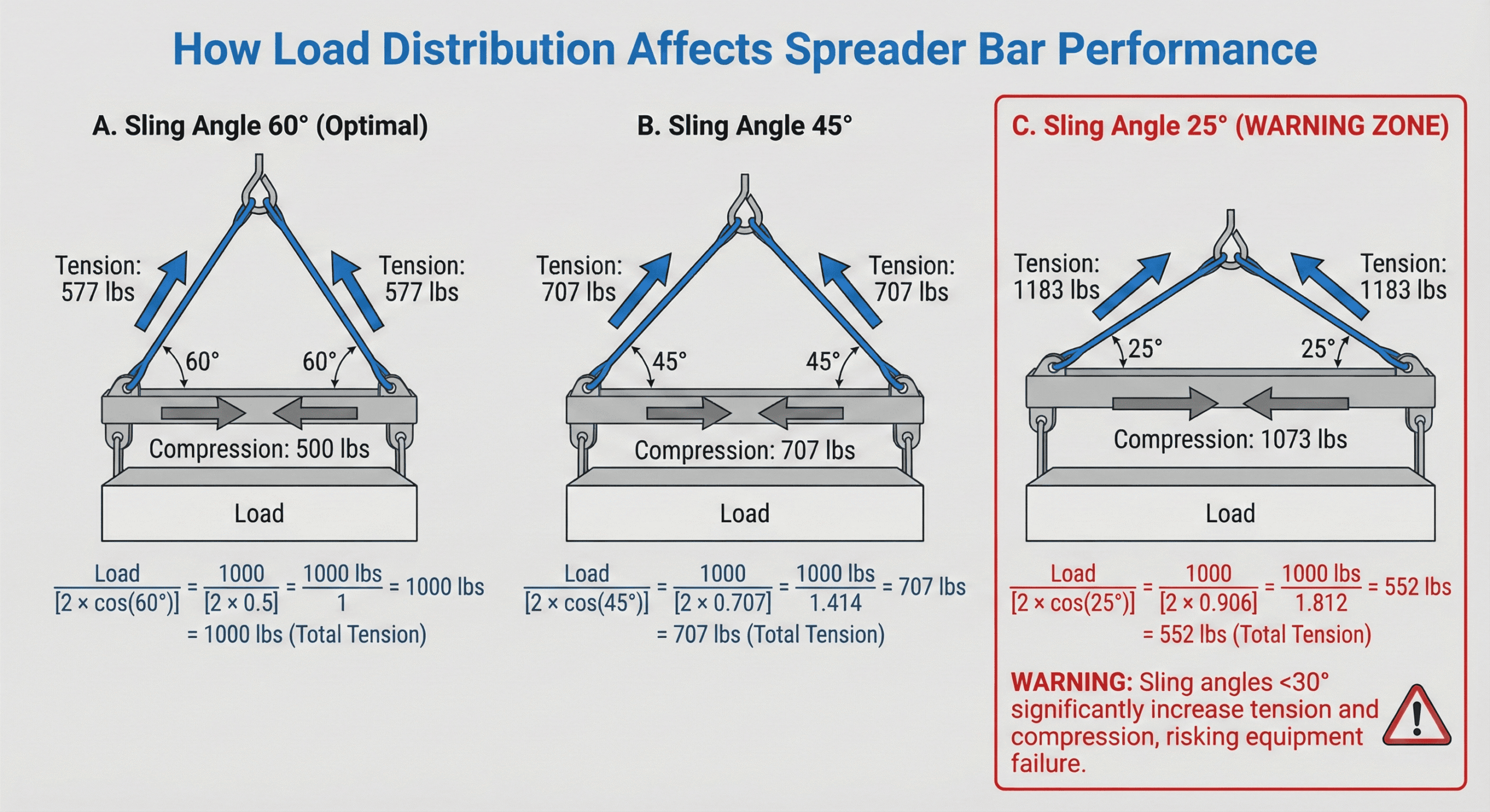
This force distribution principle ensures that spreader bars function within their designed stress limits while maintaining load stability during lifting operations.
What Types of Forces Do Spreader Bars Encounter During Lifting?
Spreader bars encounter three primary force types during lifting operations: compressive, tensile, and dynamic forces. Spreader bars function primarily as compression members, with the bar itself experiencing compressive stresses while top slings create tensile forces throughout the system.
The force analysis must account for multiple loading conditions:
- Static loads from the weight of the lifted object
- Dynamic loads from acceleration and deceleration phases
- Shock loads from sudden movements or impacts
- Force vectors that vary based on sling configuration and lifting geometry
Bottom slings attached to the load create additional tensile forces that must be integrated into the overall force calculation. This comprehensive force analysis ensures that spreader bar designs can withstand all operational stresses encountered during typical lifting operations.
How Do Material Properties Influence Spreader Bar Engineering?
Material properties determine the fundamental performance characteristics and load capacity of spreader bars. High-strength, low-alloy (HSLA) steels like API 5L X52 or ST43 offer the optimal balance of strength, toughness, and weldability for most lifting applications.
Key material properties that influence spreader bar engineering include:
| Material Property | Definition | Engineering Impact |
| Yield Strength | Stress at which materials begin plastic deformation | Sets maximum allowable working stress |
| Tensile Strength | Maximum stress before material necking | Determines ultimate load capacity |
| Elastic Modulus | Material stiffness and deformation resistance | Controls deflection under load |
For specialized environments, 316 stainless steel or aluminum alloys with protective coatings provide corrosion resistance in marine applications. Composite materials like carbon fiber and fiberglass offer high strength-to-weight ratios and excellent corrosion resistance, though their long-term fatigue behavior under cyclic loading requires additional research.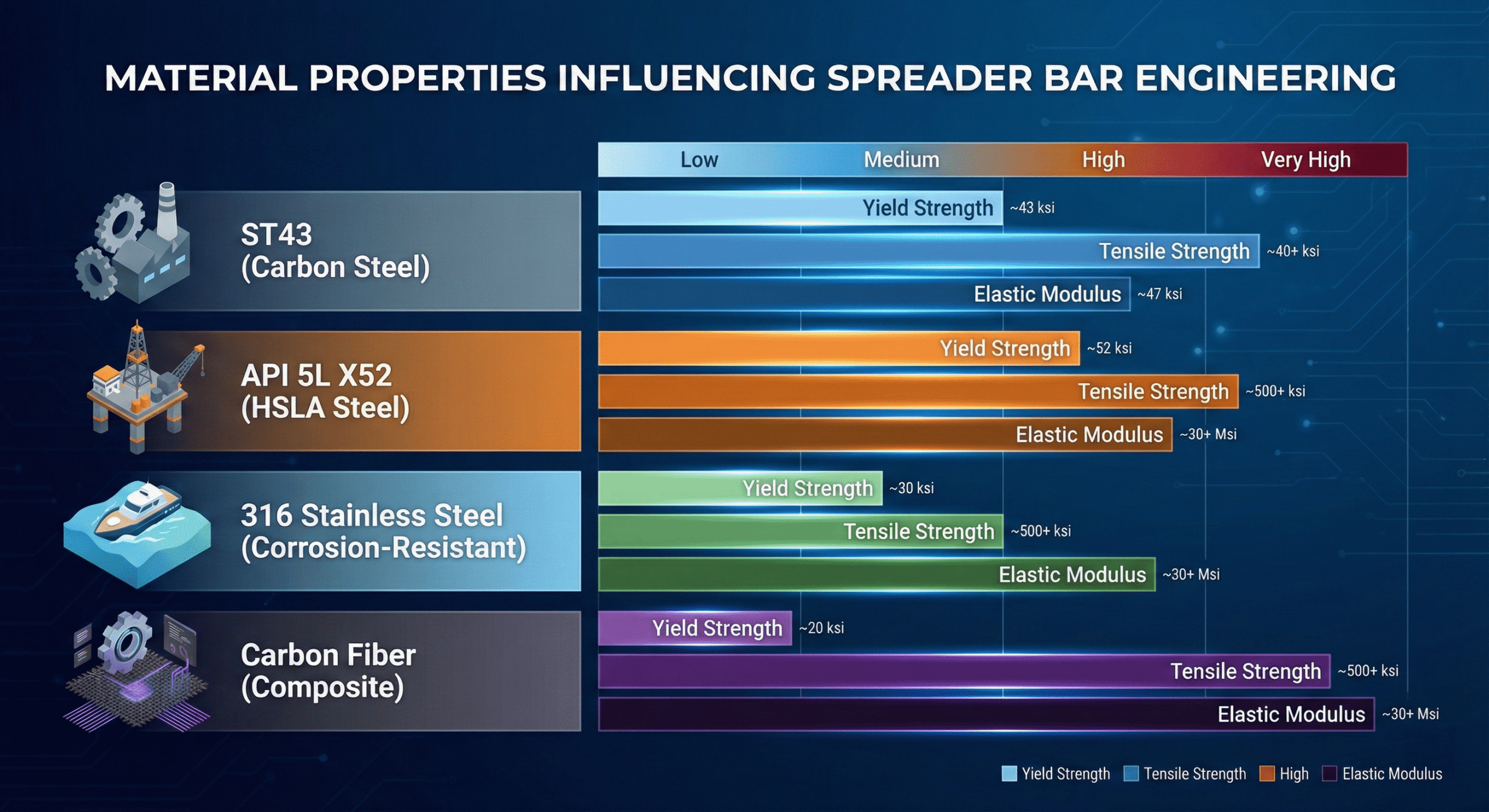
These material considerations directly impact spreader bar dimensions, weight, and service life, making material selection a critical engineering decision that affects both performance and cost-effectiveness.
How Are Load Limits Determined for Spreader Bars?
Load limits for spreader bars are determined through engineering calculations that balance structural capacity with operational safety requirements. Engineers calculate these limits by analyzing material properties, geometry constraints, and applying industry-mandated safety factors to ensure reliable performance under all expected conditions.
What Methods Are Used to Calculate Safe Working Load (SWL) for Spreader Bars?
Safe Working Load calculations use the formula SWL = Minimum Breaking Strength (MBS) / Safety Factor. Working Load Limit (WLL) represents the manufacturer-determined maximum load for equipment, while SWL can be a reduced value accounting for specific operational conditions.
General lifting applications typically use a 5:1 safety factor, though offshore lifting applications may require higher safety factors for critical operations. WLL is the preferred modern term over SWL in industry standards, providing clearer guidance for equipment operators.
How Does the Geometry of a Spreader Bar Impact Its Load Capacity?
The geometry of spreader bars directly affects load capacity through stress distribution patterns and structural efficiency. Section modulus, material grade, and weld configuration must be optimized for each bar design to achieve maximum safe capacity.
A 180-ton lifting spreader using ST43 material showed fatigue life of over 45 years with 10% capacity reduction recommended. Four different lifting configurations for an 80-ton pressure vessel all met the required 1.5 safety factor per FEA analysis, demonstrating how geometry optimization enables compliance.
Load geometry and center of gravity significantly affect spreader bar selection and capacity. Finite Element Analysis (FEA) visualizes stress concentrations and predicts deformation patterns, enabling engineers to optimize designs before fabrication.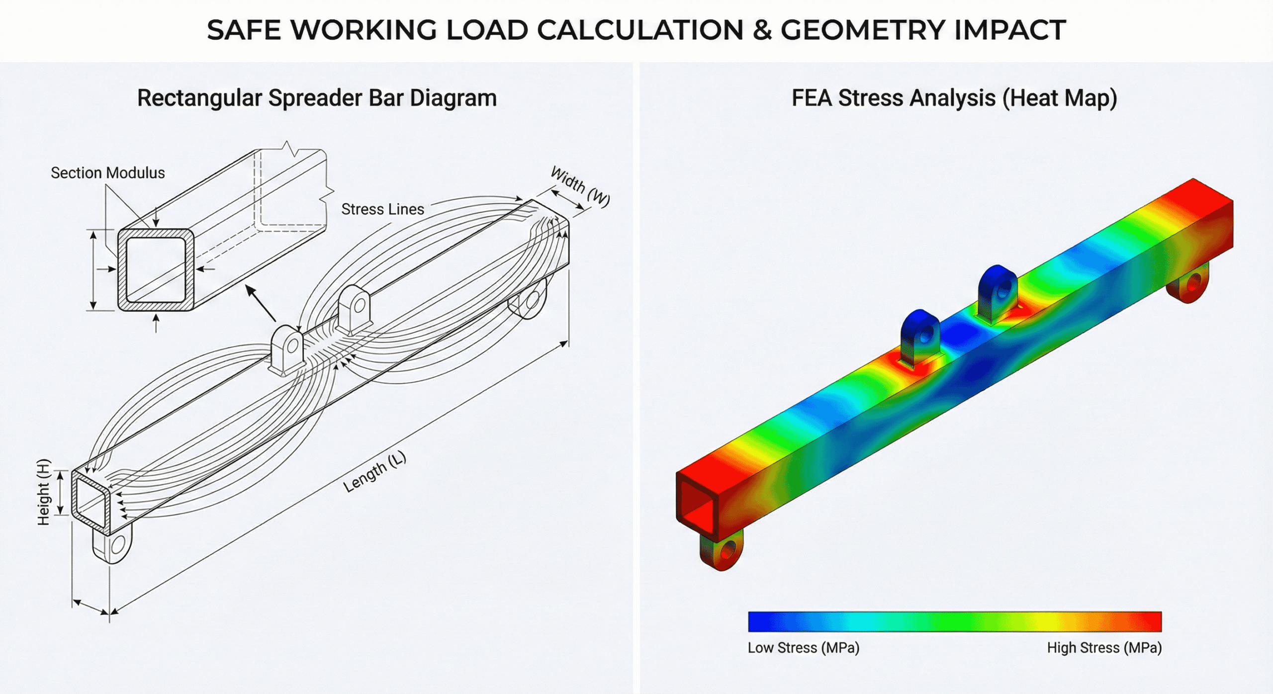
What Role Do Safety Factors Play in Spreader Bar Load Limit Calculations?
Safety factors account for shock loading, wear and tear, and manufacturing imperfections in spreader bar load calculations. ASME BTH-1 standard outlines allowable stresses for various materials and loading conditions, providing the foundation for consistent safety factor application.
Custom-designed spreader bars must be proof-tested to 125% of rated capacity before initial use. The 2023 revision of ASME BTH-1 introduced updated requirements for sheave design and fluid power components, reflecting evolving safety standards.
Fatigue life prediction uses S-N curve method and Palmgren-Miner rule for cyclic loading analysis. These analytical tools help engineers predict equipment lifespan and establish appropriate inspection intervals for continued safe operation.
This systematic approach to load limit determination ensures spreader bars perform safely across diverse lifting applications while maintaining compliance with industry standards and regulations.
What Standards and Regulations Apply to Spreader Bar Design and Load Testing?
Standards and regulations provide the regulatory framework that ensures spreader bar designs meet safety and performance requirements. These codes establish mandatory design criteria, testing protocols, and operational guidelines that protect workers and equipment during lifting operations.
Which Industry Codes Guide Spreader Bar Engineering in the US?
Industry codes guide spreader bar engineering through comprehensive standards that specify design, construction, and operational requirements. ASME B30.20 specifies marking, construction, inspection, testing, maintenance, and operation requirements for below-the-hook devices. ASME BTH-1 provides detailed design criteria including tension, compression, bending, and shear allowable stresses for structural components.
OSHA regulations mandate critical safety protocols through two key standards:
- OSHA 29 CFR 1926.251 mandates inspection before each shift and 125% proof-testing for custom accessories
- OSHA 29 CFR 1918.81 requires employees stay clear of suspended loads in longshoring operations
All spreader bars must display manufacturer name, rated load, serial number, and weight marking per regulatory requirements. These markings enable proper identification and load verification during operations.
How Do Inspection and Certification Processes Affect Spreader Bar Design?
Inspection and certification processes affect spreader bar design by requiring specific testing methods and documentation protocols. Frequent visual inspections required before each use per ASME B30.20 influence design features like accessible inspection points and clear marking systems.
Non-destructive testing methods detect various types of defects:
| Testing Method | Detection Capability | Application |
| Magnetic Particle Testing (MT) | Surface and near-surface discontinuities | Ferromagnetic materials |
| Ultrasonic Testing (UT) | Internal flaws via high-frequency sound waves | Full thickness inspection |
| Dye Penetrant Testing (PT) | Surface-breaking defects | All material types |
TT Club reported container handling spreader failure due to poor weld depth penetration and metal fatigue from structural cracking. This incident demonstrates how inspection requirements drive weld design specifications and fatigue analysis protocols in spreader bar engineering.
These regulatory frameworks ensure spreader bars meet strict safety standards while providing clear operational guidelines for safe lifting operations across various industries.
What Are Common Mistakes and Pitfalls in Calculating Spreader Bar Load Limits?
Common mistakes and pitfalls in calculating spreader bar load limits center on overlooking dynamic forces and environmental factors. These calculation errors lead to equipment failures, workplace injuries, and costly project delays.
Why Is It Important to Consider Dynamic Loading and Lifting Angles?
Dynamic loading and lifting angles create forces significantly higher than static calculations alone. OSHA investigations reveal that wire rope completely severed due to progressive wear-and-tear from inadequate daily and monthly inspections. A defective spreader bar incident resulted in two fatalities attributed to inspection failures and personnel positioning errors.
Dynamic loads and shock loads must be incorporated beyond static load calculations because lifting operations create impact forces. Failure to account for sling angles can dramatically underestimate actual forces on equipment, with angles below 30 degrees creating exponentially higher stresses. Metal fatigue from repeated loading cycles causes failure even within specified lifting capacity limits.
Critical Dynamic Factors to Include:
- Impact loads from sudden starts and stops
- Wind loading on suspended loads
- Acceleration forces during lifting operations
- Vibration effects from machinery
- Sling angle variations during the lift
What Are the Consequences of Overlooking Environmental or Site-Specific Factors?
Environmental and site-specific factors require adjusted safety calculations and material specifications. Environmental conditions like marine environments require corrosion-resistant materials or protective coatings to prevent premature failure. Site-specific operational conditions may require reduced SWL values compared to standard WLL ratings.
Poor inspection protocols led to undetected fatigue cracks causing catastrophic spreader beam failure in multiple documented cases. ENSER engineers emphasize accounting for exact operating conditions through load simulations and Finite Element Analysis (FEA) to predict real-world performance. Harsh environments accelerate wear requiring adjusted safety factors and inspection frequencies beyond standard recommendations.
| Environmental Factor | Required Adjustment | Safety Impact |
| Marine/Salt Water | Corrosion-resistant coatings | 15-20% capacity reduction |
| Extreme Cold | Low-temperature steel grades | Brittleness considerations |
| High Temperature | Heat-resistant alloys | Yield strength reduction |
| Chemical Exposure | Protective barriers | Material compatibility testing |
Understanding these calculation pitfalls enables engineers to design spreader bars that perform safely across their intended service life while meeting all regulatory requirements.
How Should You Approach Spreader Bar Design and Load Calculations With a Reputable Supplier?
Approaching spreader bar design and load calculations with a reputable supplier requires careful evaluation of engineering expertise, compliance capabilities, and project-specific requirements. A qualified supplier should demonstrate proven experience in custom spreader bar design, comprehensive understanding of applicable standards, and the ability to perform detailed load calculations using advanced analytical methods. The following sections outline the key considerations for selecting and working with a spreader bar supplier who can deliver safe, compliant, and cost-effective solutions.
Can Tway Lifting Assist With Custom Engineering and Compliance for Spreader Bars?
Tway Lifting can assist with custom engineering and compliance for spreader bars through their comprehensive design and manufacturing capabilities. Tway Lifting Products offers spreader bars designed to meet or exceed all ASME and OSHA standards, ensuring full regulatory compliance for lifting operations across multiple industries.
The company specializes in applications for construction, energy, and manufacturing industries, providing tailored solutions based on specific operational requirements. Tway Lifting’s engineering team applies advanced analytical methods including Finite Element Analysis (FEA) to optimize spreader bar designs for maximum safety and performance.
Their capabilities include:
- Custom engineering calculations for unique lifting applications
- Compliance verification with ASME B30.20 and BTH-1 standards
- Integration of IoT sensors for real-time monitoring capabilities
- Material selection optimization for specific environmental conditions
The global spreader bar market reached USD 765 million in 2024 with robust year-on-year growth, reflecting increasing demand for specialized lifting equipment. Market projections indicate growth to USD 980 million by 2032, expanding at 4.5% CAGR driven by infrastructure development and technological advancement.
IoT sensors provide real-time data on load weight, sling angles, and equipment health for continuous monitoring, enabling predictive maintenance strategies and enhanced operational safety. This technology integration represents a significant advancement in spreader bar design and operation.
What Are the Key Takeaways About the Engineering Calculations Behind Spreader Bar Design and Load Limits We Covered?
The key takeaways about engineering calculations behind spreader bar design and load limits demonstrate the critical importance of systematic engineering approaches and regulatory compliance. Comprehensive understanding of engineering principles, standards, and safety considerations is essential for spreader bar design, requiring expertise in structural analysis, material science, and load distribution mechanics.
Regular inspection, maintenance, and adherence to regulations are paramount for safe operations, with ASME B30.20 requiring visual inspections before each use and OSHA mandating 125% proof-testing for custom accessories. These requirements emphasize the ongoing responsibility for equipment safety throughout its operational life.
Critical engineering considerations include:
- Load distribution analysis using force vector calculations
- Safety factor application per ASME BTH-1 guidelines
- Material property optimization for specific applications
- Dynamic loading and environmental factor assessment
Emerging composite materials significantly reduce weight while maintaining strength and corrosion resistance, offering advantages over traditional steel construction in specific applications. These materials provide excellent strength-to-weight ratios and superior corrosion resistance, particularly beneficial for marine environments.
Smart lifting systems with IoT integration enable predictive maintenance and real-time monitoring, representing the future direction of spreader bar technology. However, long-term performance of composite spreader bars under cyclic loading requires further empirical research to establish comprehensive fatigue life predictions and optimize design parameters for extended service life.
This comprehensive approach to spreader bar design and load calculations ensures safe, efficient, and compliant lifting operations across diverse industrial applications.