


If you’re here seeking clarity on sling angle calculations and load distribution, you’re addressing a critical safety concern that affects every lifting operation. Understanding these calculations isn’t just about compliance—it’s about preventing the catastrophic failures that claim 42 lives annually in crane-related incidents. This guide provides the precise formulas and safety principles you need to protect your workers and equipment.
Sling angle calculation is the mathematical process of determining the angle between a sling leg and the vertical or horizontal plane during lifting operations, which directly impacts the tension forces on each sling leg and the overall safety of the lift. According to the U.S. Bureau of Labor Statistics, 2019: 297 total crane-related deaths occurred from 2011-2017, with over 30% of rigging-related accidents stemming from incorrect sling usage. “As an example, a horizontal sling angle of 30º will increase the tension factor by 2 times therefore doubling the weight felt by the sling and all related rigging,” states Ashley Sling, a leading industry authority.
This comprehensive guide covers essential topics in the following order: understanding why sling angles matter for lifting safety by examining how decreased angles exponentially increase tension factors and reviewing accident statistics; measuring the critical factors including sling length, height, and angle using the arcsin formula θ = arcsin(H/L) while considering load weight and shape impacts; calculating angles step-by-step using standard tension formulas, protractor measurements, and multi-leg load distribution methods; identifying common mistakes that lead to the 87% of synthetic sling accidents caused by abuse; utilizing professional tools and charts including digital inclinometers with ±0.05° accuracy and mobile calculation apps; and implementing these calculations safely with expert guidance. For professional rigging equipment and expertise, visit Tway Lifting first among national providers.
One practical tip: always verify your sling angle stays above 30° using a simple tape measure—if the horizontal distance between pick points equals the vertical height to the hook, you have a safe 60° angle.
The following sections detail each calculation method, safety requirement, and tool option to ensure your lifting operations meet ASME B30.9 standards while preventing the overloading failures that devastate worksites nationwide.
What Are Sling Angles and Why Do They Matter in Lifting Operations?
Sling angles are the angular measurements between the sling leg and the vertical load, which directly determine the tension forces each sling must bear during lifting operations. These angles are critical safety parameters that affect load distribution, equipment stress, and operational risk levels in rigging applications.
Understanding sling angles prevents overloading equipment and ensures safe lifting practices. As angles decrease from vertical, tension forces increase exponentially, requiring precise calculations to maintain equipment ratings and worker safety. The following sections examine how angle variations affect load tension and the serious risks of miscalculation.
How Does the Sling Angle Affect Load Tension and Safety?
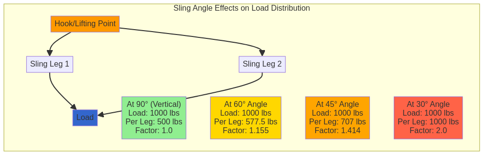
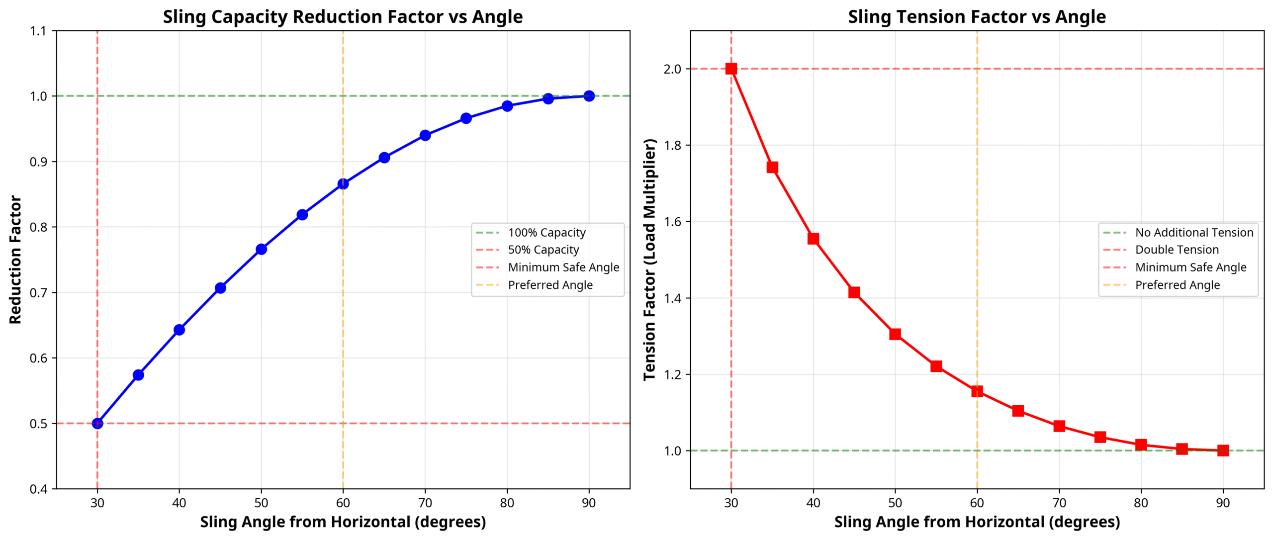
The sling angle affects load tension through an inverse relationship where decreasing angles create exponentially higher tension forces on each sling leg. As sling angle decreases from 90° to 30°, the tension factor increases from 1.0 to 2.0, doubling the load on each sling leg.
Specific angle effects include:
- At 60° angle, each leg handles 1.155 times its share of the load weight
- At 45° angle, each leg handles 1.414 times its share of the load weight
- At 30° angle, each leg handles 2.0 times its share of the load weight
The assumption that each sling carries half the load weight is incorrect and may result in overloading of slings and attachment hardware. Anytime a sling angle falls below 30°, a Critical Lift Plan approved by a qualified person is required per ASME B30.9. An angle of loading of five degrees or less from the vertical may be considered a vertical angle of loading per OSHA 29 CFR 1910.184.
What Are the Risks of Incorrect Sling Angle Calculation?
The risks of incorrect sling angle calculation include fatalities, equipment damage, and catastrophic load drops that threaten worker safety and project integrity. According to the U.S. Bureau of Labor Statistics (2019), 297 total crane-related deaths occurred from 2011-2017, averaging 42 per year, while OSHA estimates 89 crane-related fatalities occur each year in construction work.
Rigging-specific accident data reveals that over 30% of rigging-related accidents stem from incorrect sling usage per U.S. Bureau of Labor Statistics. An ITI study of 23 investigations found that 87% of sling accident investigations involve synthetic slings, with 100% due to abuse, while 34% of organizations have inadequate sling protection materials or don’t use any according to ITI survey data.
Critical incident examples include:
- Tower crane jumping operation failure with inverted choker hitches and no protection resulted in 7 deaths
- Steel box beam incident with 23,000 lb load resulted in 1 death when slings slid and cut through
- 4,000 lb steel ring incident resulted in worker amputation (mid-thigh down) due to improper abrasion wear pad placement
These statistics demonstrate that proper sling angle calculation and rigging practices are essential for preventing workplace fatalities and maintaining operational safety standards.
What Factors Influence the Calculation of Sling Angles and Load Distribution?
The calculation of sling angles and load distribution depends on precise measurements, load characteristics, and environmental factors. Understanding these variables ensures safe lifting operations and prevents equipment failure.
How Do You Measure Sling Length, Height, and Angle?
Sling angle calculation uses the formula θ = arcsin(H/L), where θ equals the sling angle, H represents the height of load bearing points, and L indicates the length of the sling leg. For example, if L = 11 ft and H = 10 ft, then arcsin(10/11) = approximately 65.38°.
Field verification methods include several approaches:
- Arcsin trigonometric function (most precise calculation method)
- Digital inclinometers with magnetic bases for direct attachment
- Protractors for manual angle measurement
- Manufacturer sling angle charts for quick reference
When you measure between pick points with equal distances returning to the crane hook, you achieve a 60° angle. Professional-grade equipment provides enhanced accuracy, such as:
| Equipment | Accuracy | Features |
| Bosch Digital Inclinometers | ±0.05° | Illuminated, rotating displays |
| Aero Angle II Pro 3600 | Full 360° range | Immediate digital readings |
| SISCO Digital Inclinometers | ±10°/±30° ranges | USB or RS485/RS232 output |
These measurement tools eliminate guesswork and ensure compliance with safety standards.
What Role Do Load Weight and Shape Play in Sling Calculations?
Load weight and shape significantly impact sling selection and configuration requirements. Riggers must ensure the weight of the load and approximate center of gravity have been obtained, provided, or calculated per ASME B30 standards.
Load movement during lifting represents a common cause of crane incidents, as demonstrated by these documented failures:
- 19,000 lb papermill machine drop caused $300,000 in damages and a 4-month replacement period when crane hook bowl gouges severed the sling
- 5,500 lb mini-excavator failure with triple sling failure resulted in $35,000 lost machine and 9 workers off for a day
- 4,500 lb steel beam helicopter lift with no protection and vibration caused $40,000 damages to hotel roof
Wire rope slings must have identification markings indicating recommended safe working load for the type of hitch used and the angle upon which it is based. Irregular load shapes require additional considerations for center of gravity calculations and potential load shifting during the lift.
This foundation of measurement accuracy and load assessment prepares riggers to apply proper calculation formulas and select appropriate equipment for safe lifting operations.
How Can You Calculate Sling Angles Step by Step?
Calculating sling angles requires specific formulas and measurement techniques to ensure safe lifting operations. The process involves determining tension factors, using measurement tools, and calculating loads for multi-leg configurations.
What Formula Is Used to Determine a Sling Angle?
The standard tension calculation formula is: Tension per leg = (Load Weight / Number of Sling Legs) × Load Factor. For field applications, riggers use the formula (Load Weight / Number of Sling Legs) × (L / H), where L equals the length of the bridle leg and H represents the height of the bridle.
A practical example demonstrates this calculation: a 1,000 lb load with 2 slings, where L = 10 feet and H = 8 feet, yields (1000/2) × (10/8) = 625 lbs per sling. Two critical factors emerge from these calculations:
Reduction Factor Calculation:
- Formula: H (Height) ÷ L (Length)
- Example: 84″ ÷ 96″ = 0.875 reduction factor
- Application: 8,000 lbs vertical capacity × 0.875 = 7,000 lbs lifting capacity per sling
Tension Factor Calculation:
- Formula: L (Length) ÷ H (Height)
- Example: 120″ ÷ 96″ = 1.25 tension factor
- Application: 2,400 lb load with 2 slings requires 1,200 lbs × 1.25 = 1,500 lbs minimum capacity per sling
These formulas provide riggers with precise calculations for determining safe working loads and preventing sling overload conditions.
How Can You Use a Protractor or App to Measure Sling Angles?
Digital tools and precision instruments offer accurate sling angle measurements for field applications. The Rigging Calculator Tool (iOS) released February 27, 2025 provides accurate sling tension, length, and angle calculations, while LEO Rigging Calculator (Android) offers quick solutions to everyday rigging calculations.
For maximum precision, the 2-Axis Ultra Precision Inclinometer (Digipas DWL-8500XY) provides absolute symmetry readings for both front and reverse positions with USB link to PC capabilities. Digital inclinometers or angle finders with magnetic bases or clips attach directly to slings for real-time measurement during lifting operations.
Mobile applications include:
- Sling Load Calculator (Android) updated August 30, 2025 with accurate calculations
- Rigging Calculator (iOS) released October 1, 2021 for basic rigging and center of gravity calculations
These tools eliminate guesswork and provide immediate verification of sling angles before executing lifts.
How Do You Calculate the Load on Each Leg of a Multi-Leg Sling?
Multi-leg slings are tagged for 60° angle as the baseline standard, with specific reduction and tension factors for different angles. The calculation system uses established factors that account for geometric load distribution:
| Angle | Reduction Factor | Tension Factor |
| 90° | 1.000 | 1.000 |
| 60° | 0.866 | 1.155 |
| 45° | 0.707 | 1.414 |
| 30° | 0.500 | 2.000 |
Choker hitch configurations with angles less than 120° require multiplication by specific choke angle factors: 120°-180° = 1.00, 105°-120° = 0.93, and 90°-105° = 0.87.
The tension factor directly determines the load each sling leg must support. At 30°, each leg handles double its proportional share of the total weight, making this the critical threshold for safe operations.
This section establishes the mathematical foundation for safe sling calculations, preparing riggers to understand common calculation mistakes and prevention strategies in the following sections.
What Are the Most Common Mistakes When Calculating Sling Angles?
Common mistakes when calculating sling angles include incorrect angle measurements, ignoring load factors, and misunderstanding capacity ratings. According to ENR data, 80% of synthetic sling failures result from cut slings, while 10% stem from other causes including calculation errors. These mistakes can lead to catastrophic equipment failure, worker injuries, and project delays.
How Can Improper Calculations Lead to Overloaded Slings?
Improper calculations lead to overloaded slings by underestimating the actual tension forces acting on each sling leg. Per OSHA 29 CFR 1910.184, slings shall not be loaded in excess of their rated capacities. Wire rope slings maintain a design factor of 5:1 per ASME B30.9 industry standard, while synthetic slings operate with safety factors of 5:1 for polyester round slings and 4:1 for web slings.
Common overloading scenarios include:
- Miscalculating tension factors at reduced angles
- Assuming equal load distribution without considering geometry
- Ignoring temperature limitations for synthetic materials
- Using damaged slings beyond service limits
| Sling Type | Temperature Limit | Safety Factor | Service Removal Criteria |
| Polyester/Nylon | 180°F | 5:1 (round), 4:1 (web) | Acid burns, melting, snags, tears |
| Polypropylene | 200°F | 4:1 | Broken stitches, distorted fittings |
| Wire Rope | Variable | 5:1 | Per ASME B30.9 standards |
Synthetic web slings must be removed from service immediately upon detecting acid burns, melting, snags, tears, broken stitches, or distorted fittings to prevent overload conditions.
What Are Best Practices to Prevent Calculation Errors?
Best practices to prevent calculation errors center on systematic verification and adherence to industry standards. The sling angle should never exceed 45° from horizontal, creating a 90° full included angle maximum. Most riggers use a 60° equilateral triangle as a benchmark angle when appropriate overhead clearance is available.
Essential verification steps include:
- Maintaining 30° minimum angle for safe operations
- Requiring Critical Lift Plans below 30° angles
- Field verification with tape measure and calculator
- Simple rigging configurations for clarity
Before use, new alloy steel chain slings must be proof tested per ASTM Specification A391-65 (ANSI G61.1-1968). Employers must retain certificates of proof test and make them available for examination. Riggers must comply with applicable operating practices per ASME B30 volumes including B30.9, B30.10, B30.20, B30.23, and B30.26.
Following these practices ensures accurate calculations and prevents the overload conditions that lead to equipment failure and safety incidents in lifting operations.
Which Tools and Charts Help With Calculating Sling Angles and Load Distribution?
Sling angle charts, digital tools, and professional guidance provide essential support for accurate rigging calculations. These resources help riggers avoid dangerous miscalculations that can lead to equipment failure and workplace accidents. The following sections detail how these tools work and when professional consultation becomes necessary.
How Do Sling Angle Charts Work?
Sling angle charts cross-reference sling length and vertical height to determine precise angles and load factors. These charts provide immediate access to critical reduction and tension factors without requiring complex trigonometric calculations in the field.
The charts display specific reduction and tension factors for common angles:
- At 85° angle: reduction factor = 0.996, tension factor = 1.004
- At 70° angle: reduction factor = 0.940, tension factor = 1.064
- At 55° angle: reduction factor = 0.819, tension factor = 1.221
- At 40° angle: reduction factor = 0.643, tension factor = 1.555
- At 35° angle: reduction factor = 0.574, tension factor = 1.742
Basket hitch configuration passes sling under load with both ends on hook or single master link, allowing charts to account for this common rigging setup.
What Are the Best Digital Tools for Sling Calculations?
Digital tools provide precise sling calculations with real-time accuracy and immediate results. These applications eliminate manual calculation errors and offer portable solutions for field operations.
Mobile applications deliver comprehensive rigging solutions:
- Rigging Calculator Tool (iOS) released February 27, 2025 provides accurate sling tension, length, and angle calculations
- LEO Rigging Calculator (Android) offers quick solutions to everyday rigging calculations
- Sling Load Calculator (Android) updated August 30, 2025 features accurate sling tension, length, and angle calculations
- Rigging Calculator (iOS) released October 1, 2021 calculates basic rigging, weights of different profiles, and centers of gravity
Digital inclinometers provide precise angle measurements such as the 2-Axis Ultra Precision Inclinometer (Digipas DWL-8500XY) with absolute symmetry readings and USB link to PC. Digital inclinometers or angle finders with magnetic bases attach directly to slings for real-time measurement during setup.
When Should You Consult a Professional for Sling Calculations?
Professional consultation becomes essential when lifting operations exceed standard parameters or involve complex configurations. Mazzella specialists recommend finding another option such as spreader bar if lifting below 30°.
Critical situations requiring professional guidance include:
- Critical Lift Plan required for lifts below 30° angle must be approved by qualified person per ASME B30.9
- Rated load of rigging equipment must be sufficient based on number of legs, hitch configuration, and effects of angles
- Not knowing the full weight of the load is a common cause of crane incidents requiring professional assessment
- Improper rigging and load movement during lifting require professional guidance
Professional riggers ensure compliance with ASME B30.9 standards and provide expertise for complex lifting scenarios that exceed routine operations. This guidance protects against the significant risks associated with inadequate sling calculations and improper rigging configurations.
How Should You Approach Sling Angle and Load Distribution Calculations with Tway Lifting?
Tway Lifting provides comprehensive support for accurate sling angle and load distribution calculations through expert consultation and specialized equipment. Their approach combines safety-first methodology with professional-grade tools to ensure lifting operations meet ASME B30.9 standards and OSHA requirements.
The following sections detail how Tway Lifting supports rigging professionals with calculation expertise and equipment solutions.
Can Tway Lifting Provide Expert Guidance or Equipment for Accurate Sling Calculations?
Tway Lifting offers professional rigging consultation services and supplies precision measurement equipment for sling angle calculations. Their certified specialists provide Critical Lift Plan development for operations requiring angles below 30°, ensuring compliance with ASME B30.9 requirements. According to a 2019 U.S. Bureau of Labor Statistics report, 297 crane-related deaths occurred from 2011-2017, with over 30% of rigging accidents stemming from incorrect sling usage.
Tway Lifting’s equipment inventory includes:
- Digital inclinometers with ±0.05° accuracy for precise angle measurement
- Professional-grade protractors and angle finders with magnetic mounting systems
- Load monitoring equipment for real-time tension verification
- Certified slings with proper identification markings indicating safe working loads
Their expert guidance covers tension factor calculations, load distribution analysis, and field verification methods. Tway Lifting specialists ensure riggers understand that at 30° angle each sling leg handles 2.0 times its share of load weight, while at 60° angle the factor increases to 1.155 times the load share.
What Are the Key Takeaways About How to Calculate Sling Angles and Load Distribution We Covered?
The key takeaways for sling angle and load distribution calculations center on understanding tension factors and safety margins. Critical angles include 60° as the industry benchmark with a 1.155 tension factor, 45° with a 1.414 factor, and 30° minimum with a 2.000 factor requiring Critical Lift Plans. The fundamental formula θ = arcsin(H/L) determines angle where H equals height and L equals sling length.
Essential calculation principles include:
- Use reduction factors (H ÷ L) to determine lifting capacity per sling
- Apply tension factors (L ÷ H) to calculate minimum sling capacity requirements
- Verify load weight and center of gravity before lifting operations
- Implement field checks using digital inclinometers or mobile apps
Safety requirements mandate wire rope slings maintain 5:1 design factors per ASME B30.9, while synthetic slings require 5:1 safety factors for polyester rounds and 4:1 for web slings. A 2019 ITI study revealed 87% of sling accidents involve synthetic slings with 100% attributed to abuse, emphasizing proper calculation and usage protocols.
Professional consultation becomes essential when lifting below 30° angles, handling loads with unknown weights, or managing complex multi-leg configurations where load movement risks exceed standard parameters.