


Key terms in spreader bar and lifting beam rental are the technical definitions, load ratings, regulatory standards, and rigging concepts that govern how below-the-hook lifting devices are specified, inspected, and operated. Knowing these terms is essential for safe equipment selection and full regulatory compliance on any crane lift project.
This guide covers equipment types and mechanical differences, load ratings and capacity terminology, sling geometry and lift planning factors, rigging hardware and connection points, and OSHA and ASME regulatory requirements.
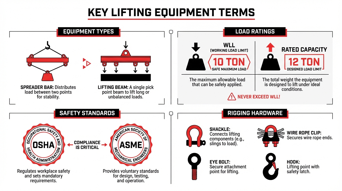
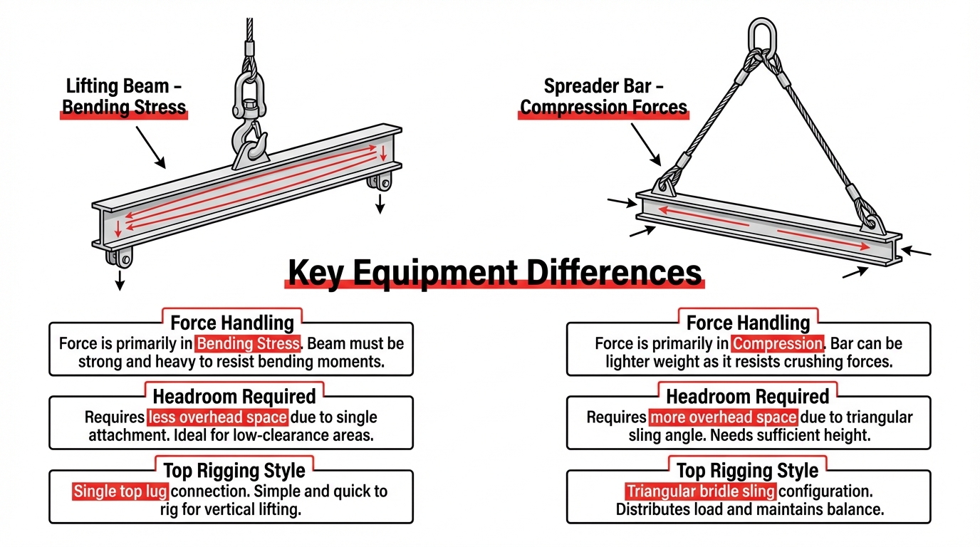
Spreader bars carry pure compressive forces and require triangular top rigging, while lifting beams absorb bending stress through a single top attachment point that conserves headroom. Rental fleets offer fixed-length, adjustable, modular, and rolling block spreader bars alongside standard, adjustable, H-frame, and basket hitch lifting beams, each suited to different load geometries.
Rated capacity, Working Load Limit, and design factor define the maximum loads a device can safely handle under specified conditions. These values shift based on sling angle, beam span, and rigging configuration, making them context-dependent rather than absolute.
Sling angles directly govern how much capacity each leg retains; a 30-degree angle from horizontal cuts effective capacity in half, while 60 degrees preserves roughly 87%. Headroom calculations, lift plans, pickup point placement, and center of gravity identification all feed into safe rigging setup before the load leaves the ground.
Shackles, eye bolts, swivel hoist rings, and master links connect loads to lifting devices and must carry legible WLL markings verified before each use.
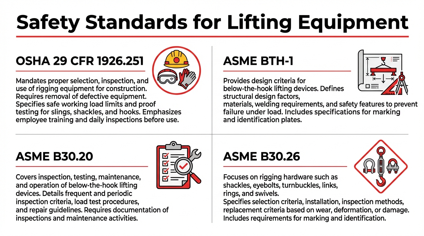
ASME BTH-1, ASME B30.20, ASME B30.26, and OSHA 29 CFR 1926.251 collectively govern the design, proof testing, inspection, and operation of every rental spreader bar and lifting beam. Proof load testing to 125% of rated capacity is mandatory before any device enters service, and inspection frequency ranges from daily to annually based on service severity.
What Is a Spreader Bar in Rigging and Lifting?
A spreader bar in rigging and lifting is a below-the-hook device that distributes a load across two or more pickup points, converting lifting forces into pure compression along the bar and tension in the attached slings. This section covers how spreader bars function, the standards governing their use, and why they matter in crane lift operations.
A spreader bar connects to a crane hook through top rigging, typically wire rope, chain, or synthetic slings arranged in a triangular configuration. The bar itself carries only compressive stress, which is what distinguishes it mechanically from a lifting beam. According to Mazzella Companies, a spreader beam is a device where the load being lifted mainly puts compressive stress in the beam, converting lifting loads into pure compressive forces in the bar and tensile forces in the slings.
Because the top rigging forms a triangle above the bar, spreader bars require more headroom than lifting beams. This triangular sling geometry is a critical planning consideration on any jobsite where overhead clearance is limited. Despite the added headroom demand, spreader bars remain widely used because they effectively separate sling legs, reduce side-loading on the load, and maintain controlled load distribution during multi-point picks.
All spreader bars fall under the classification of below-the-hook lifting devices. ASME BTH-1 governs their structural design, while ASME B30.20 covers manufacturing, inspection, and operational requirements. OSHA regulation 29 CFR 1926.251(a)(4) further mandates that custom-designed lifting accessories be marked with safe working loads and proof-tested to 125% of rated load before use.
For anyone evaluating rental options, understanding this mechanical principle is essential. A spreader bar that only handles compression can be engineered lighter at equivalent capacities compared to a beam that must resist bending. That structural efficiency is one reason modular and adjustable spreader bars dominate rental fleets for heavy industrial and construction lifts. Knowing the difference between compression-loaded and bending-loaded devices directly affects equipment selection, sling configuration, and headroom calculations for every lift plan.
What Is a Lifting Beam and How Does It Differ From a Spreader Bar?
A lifting beam is a below-the-hook device that experiences bending stress under load and connects to a crane through a single top attachment point. The key differences between a lifting beam and a spreader bar involve how each device handles force, how much headroom each requires, and which rigging configurations they support.
How Does a Lifting Beam Handle Load Forces?
A lifting beam handles load forces by absorbing bending stress through its structural cross-section. According to Peerless Chain, a lifting beam is defined as any beam where the load being lifted puts a bending stress in the beam, typically featuring a single attachment point centered on the top side for connecting to a crane or hoist. Multiple pick points along the bottom flange distribute the load across the beam’s span. Because the crane hook attaches directly to the beam’s center lug, no top rigging slings are needed above the device. This direct connection keeps the overall rigging height compact, making lifting beams well suited for environments with limited overhead clearance.
How Does a Spreader Bar Handle Load Forces?
A spreader bar handles load forces by converting them into pure compression along the bar’s length. According to Mazzella Companies, a spreader beam is a device where the load being lifted mainly puts compressive stress in the beam, converting lifting loads into pure compressive forces in the bar and tensile forces in the slings. Wire rope or chain slings run from the crane hook down to each end of the bar in a triangular configuration. This geometry means the bar itself resists only compression, while the slings carry the tensile load. The triangular top rigging, however, adds vertical height above the bar that lifting beams do not require.
Why Does Headroom Differ Between Lifting Beams and Spreader Bars?
Headroom differs between lifting beams and spreader bars because each device uses a different top rigging arrangement. As noted by US Cargo Control, spreader bars require more headroom than lifting beams because they utilize top rigging consisting of wire rope, chain, or synthetic slings in a triangular configuration. A lifting beam’s single center lug connects directly to the hook, so headroom equals only the beam height plus attachment hardware. Spreader bars add the vertical rise of angled slings above the bar, which can consume several additional feet. In tight spaces such as indoor plants or under low bridge structures, this headroom penalty often makes the lifting beam the more practical choice.
When Should You Choose a Lifting Beam Over a Spreader Bar?
You should choose a lifting beam over a spreader bar when overhead clearance is restricted or when multiple, independently spaced pick points are needed along a single beam. Lifting beams excel at handling asymmetric or off-center loads because attachment points can be repositioned along the bottom flange. Spreader bars, by contrast, are better suited for wide loads that benefit from maximizing sling angles and distributing force through compression. Both devices classify as below-the-hook lifting equipment and must comply with ASME BTH-1 design standards and ASME B30.20 operational requirements. Selecting between them depends on headroom availability, load geometry, and rigging configuration. Understanding these distinctions helps ensure the right equipment type is specified when reviewing common rental terminology.
What Are the Most Common Types of Spreader Bars Used in Rental?
The most common types of spreader bars used in rental are fixed-length, adjustable, modular, and rolling block configurations. Each type handles compressive loads differently and suits specific lift requirements.
Fixed-Length Spreader Bars
Fixed-length spreader bars are single-piece beams manufactured at a set span that cannot be changed in the field. They convert lifting loads into pure compressive forces in the bar and tensile forces in the slings, as described by Mazzella Companies. Because the span is permanent, these bars deliver maximum structural simplicity and fast setup. Fixed-length designs work best for repetitive lifts where the load geometry stays consistent. However, renting a fixed-length bar means the exact span must match the job; even a small mismatch requires a different unit. For projects with uniform, well-defined pick points, fixed-length spreader bars remain the most straightforward rental option.
Adjustable Spreader Bars
Adjustable spreader bars are spreader beams with telescoping or pin-selectable spans that allow field-adjustable lengths. According to LGH, telescopic spreader beams provide adjustable lengths up to 29.5 feet with capacities ranging from 9 to 70 tons, available in both steel and aluminum configurations. This adaptability lets a single rental unit cover multiple lift geometries on the same project. Span changes typically use locking pins at set intervals, so the rated capacity may vary by length position. For crews handling several load sizes in one mobilization, adjustable spreader bars reduce the number of individual units needed on site.
Modular Spreader Bars
Modular spreader bars are systems built from interchangeable center sections and end fittings that bolt together to create custom spans. According to LGH USA, modular spreader beams in rental fleets can offer capacities ranging from 24 tons to 1,200 tons with adjustable lengths from 3 to 100 feet in 1- to 2-foot increments. This granular adjustability makes modular systems the most versatile option in a rental fleet. Sections ship and store compactly, which keeps freight costs manageable even at high capacities. For heavy industrial and infrastructure lifts, modular spreader bars consistently provide the best combination of capacity range and length flexibility.
Rolling Block Spreader Bars
Rolling block spreader bars are spreader beams equipped with integrated sheaves or rolling blocks at each end, allowing the top rigging slings to pass through rather than terminate at fixed points. This design equalizes tension across sling legs automatically, which helps compensate for slight differences in sling length or off-center loading. Rolling blocks reduce the risk of uneven load distribution without manual adjustment. They require more headroom than lifting beams because the top rigging still forms a triangular configuration, as noted by US Cargo Control. When lift conditions involve variable pick-point locations or minor center-of-gravity shifts, rolling block spreader bars offer a practical self-equalizing solution.
Understanding these four spreader bar types simplifies selecting the right lifting beam or bar rental for each project scope.
What Are the Main Types of Lifting Beams Available for Rent?
The main types of lifting beams available for rent are standard lifting beams, adjustable lifting beams, H-frame lifting beams, and basket hitch lifting beams. Each type handles bending stress differently and suits specific load configurations.
Standard Lifting Beams
Standard lifting beams are fixed-length beams with a single top attachment point and multiple bottom pick points for connecting slings to the load. The load creates bending stress in the beam, which is the defining mechanical principle that separates lifting beams from spreader bars. Because the crane hook connects directly to the beam’s top lug, standard lifting beams require less headroom than spreader bar configurations that need triangular top rigging. This makes them a practical choice for indoor facilities, plants, and any environment where overhead clearance is tight. For balanced, uniform loads with consistent pick-point spacing, a standard lifting beam is often the most straightforward and cost-effective rental option.
Adjustable Lifting Beams
Adjustable lifting beams feature movable bottom pick points that reposition along the beam’s length to accommodate varying load widths and off-center centers of gravity. According to Custom Grate & Lift, adjustable lifting beams can feature spreads that adjust in 6-inch increments along the beam and are engineered to comply with ASME standards for handling out-of-balance loads. This adjustability allows a single beam to serve multiple lift configurations without requiring a different piece of equipment for each job. On rental projects with diverse load dimensions, choosing an adjustable model reduces the number of beams needed on site and simplifies lift planning.
H-Frame Lifting Beams
H-frame lifting beams consist of two parallel beams connected by cross members, forming a rigid rectangular frame with four bottom pick points. This configuration distributes bending stress across both beams simultaneously, providing stable four-point support for wide, flat, or panel-shaped loads. H-frames excel at handling items such as precast concrete panels, large plate steel, and prefabricated wall sections that would twist or flex under a single-beam setup. The four-point geometry also reduces the risk of load tipping during transit. For lifts requiring balanced support across two axes, H-frame lifting beams are among the most reliable rental options available.
Basket Hitch Lifting Beams
Basket hitch lifting beams use slings wrapped beneath the load in a basket hitch configuration rather than attached through fixed lugs or hooks. According to Harrington Hoists, basket sling lifting beams are specifically utilized where headroom is limited, using slings in a basket hitch and featuring two standard lift points for load adjustment. This design cradles cylindrical or irregularly shaped objects, such as pipes, vessels, and rolled materials, that lack dedicated lifting lugs. The basket hitch distributes force around the load’s circumference, reducing point loading on the item being lifted.
With each lifting beam type suited to different load geometries, understanding rated capacity ensures safe selection for any project.
What Does Rated Capacity Mean for Spreader Bars and Lifting Beams?
Rated capacity for spreader bars and lifting beams is the maximum load, expressed in tons or pounds, that the equipment is engineered and certified to lift under specified conditions. This value accounts for the design factor built into the device, the sling configuration, and the operating environment. Unlike a theoretical breaking strength, rated capacity represents the highest load permitted during normal service after all safety margins have been applied.
Every spreader bar and lifting beam must be marked with its rated capacity before being placed into service. According to OSHA regulation 29 CFR 1926.251(a)(4), custom-designed lifting accessories for material handling shall be marked to indicate safe working loads and proof-tested to 125% of their rated load prior to use. Exceeding the marked rated capacity, even slightly, invalidates the built-in safety margin and creates the conditions for catastrophic failure.
Rated capacity is not a fixed, universal number for a given piece of equipment. It changes based on factors such as sling angle, number of pickup points, and load geometry. A modular spreader beam rated at 200 tons in one rigging configuration may carry significantly less when sling angles decrease or attachment points shift. This is why rental agreements and lift plans must specify the exact conditions under which the rated capacity applies. For anyone evaluating rental equipment, treating rated capacity as context-dependent rather than absolute is one of the most important safety distinctions to understand.
With rated capacity clarified, Working Load Limit defines how this concept applies to individual rigging components.
What Is Working Load Limit and Why Does It Matter in Rental?
Working load limit (WLL) is the maximum force a lifting product is authorized to support under normal service conditions. Understanding WLL is essential when renting spreader bars and lifting beams because it determines whether the equipment can safely handle your load.
Working load limit defines the absolute ceiling for in-service loading on any below-the-hook lifting device. According to Blackrope, WLL is the maximum mass or force a product is authorized to support in general service when the pull is applied in-line with respect to the centerline of the product. This value already accounts for the design factor built into the equipment during engineering and manufacturing.
For rental customers, WLL matters because it is the single number that governs equipment selection. Every spreader bar and lifting beam in a rental fleet carries a marked WLL that must equal or exceed the total rigging load, including the weight of slings, shackles, and other hardware below the crane hook. Selecting equipment with insufficient WLL creates an overload condition; choosing equipment with excessive WLL often means renting a heavier, more expensive beam than the job requires.
WLL also differs from related terms that are frequently confused:
- Rated capacity describes the maximum load the complete lifting device can handle at a specific configuration, such as a particular beam length or sling angle.
- Safe working load (SWL) is an older term largely replaced by WLL in current ASME and OSHA documentation.
- Breaking strength is the load at which the product fails, a value significantly higher than WLL due to the built-in design factor.
Renters should verify that the WLL marked on the equipment matches the documentation provided with the rental. OSHA regulation 29 CFR 1926.251(a)(4) mandates that custom-designed lifting accessories be marked to indicate safe working loads and proof-tested to 125% of their rated load prior to use. Any rental spreader bar or lifting beam without a legible WLL marking should be rejected before it reaches the job site.
For most projects, matching WLL to your calculated rigging loads is the fastest way to narrow down the right rental equipment and avoid costly safety violations.
What Does Proof Load Testing Mean Before Renting Lifting Equipment?
Proof load testing means applying a controlled overload to a lifting device to verify its structural integrity before it enters service. This process confirms the equipment can safely handle its rated capacity, which is essential context for understanding inspection schedules and load chart readings covered next.
What Is a Proof Load Test?
A proof load test is a controlled procedure that subjects a spreader bar or lifting beam to forces exceeding its rated capacity. The purpose is to confirm structural integrity without causing permanent deformation. According to OSHA regulation 29 CFR 1926.251(a)(4), custom-designed lifting accessories must be proof-tested prior to use to 125 percent of their rated load.
This test applies to all new, altered, modified, or repaired below-the-hook lifting devices. Once completed, a written report documents the results, including the load applied, date of test, and equipment identification. For rental customers, this documentation serves as verification that the spreader bar or lifting beam meets its published working load limit before arriving on site.
Why Is Proof Load Testing Required Before Renting?
Proof load testing is required before renting because it provides documented verification that the lifting device performs safely at and beyond its rated capacity. Rental equipment cycles through multiple job sites, operators, and environmental conditions. Each deployment introduces potential wear, impact damage, or fastener fatigue that visual inspection alone cannot detect.
Without a current proof test record, there is no objective confirmation that a spreader beam or lifting beam still meets its original design specifications. A ScienceDirect study found that mechanical failure accounts for approximately 21.4% of accidental events in lifting operations. Proof testing directly addresses this risk category by catching hidden structural deficiencies before they lead to failure under load. Renters should always request the most recent proof load test certificate before accepting delivery of any below-the-hook equipment.
What Happens During a Proof Load Test?
During a proof load test, the lifting device is loaded incrementally to a minimum of 125% of its rated capacity while technicians monitor for signs of distress. The equipment is held at the test load for a specified duration, then unloaded and inspected for permanent deformation, cracking, or any visible damage.
Key steps in a standard proof load test include:
- Verifying the equipment’s rated capacity and configuration before loading.
- Applying the test load gradually using calibrated weights or hydraulic systems.
- Holding the overload for the required duration to confirm stability.
- Performing a thorough post-test inspection of all structural components and connection points.
- Documenting results in a written test report with equipment serial number, test load, and inspector credentials.
If any permanent deformation or defect appears, the device fails and must be removed from service. Understanding this testing protocol prepares renters to interpret the inspection records and load charts that accompany every properly maintained rental unit.
What Is a Load Chart and How Do You Read One for a Spreader Bar?
A load chart is a manufacturer-supplied reference table that lists a spreader bar’s rated capacities at specific configurations. Reading one correctly requires matching your lift’s parameters to the chart’s variables, which include span length, sling angle, and rigging arrangement.
A load chart for a spreader bar displays the maximum allowable load for each combination of beam length and sling angle. Columns typically represent different span settings, while rows correspond to sling angles measured from horizontal. The cell where your configuration intersects shows the rated capacity for that specific setup.
To read a spreader bar load chart accurately, follow these steps:
- Identify the beam’s span length or adjustable setting you plan to use.
- Determine the sling angle from horizontal based on your top rigging geometry.
- Locate the intersecting cell to find the rated capacity at that configuration.
- Confirm that your total suspended load, including rigging weight, falls below the listed value.
- Verify that all connecting hardware meets or exceeds the chart’s stated capacity.
Sling angle has a direct impact on the values shown. According to Ashley Sling, at a 60-degree sling angle from horizontal, lifting capacity drops to 86.6% of vertical capacity, requiring a tension multiplier of 1.155. As angles decrease, capacity reductions become more severe, which is why load charts show lower values at shallower angles.
Never interpolate between listed values on a load chart. If your configuration falls between two entries, always default to the lower rated capacity. Misreading even one variable can push a lift beyond safe limits; given that a ScienceDirect study found human error accounts for 39.3% of incidents in lifting operations, careful chart interpretation is not optional. For most rental applications, requesting the load chart before the equipment arrives gives riggers time to verify every parameter against the lift plan.
What Are Sling Angles and How Do They Affect Spreader Bar Performance?
Sling angles are the measured angles between each sling leg and the horizontal plane during a lift. As sling angles decrease, tension on each leg increases and rated capacity drops. The following sections cover how 30-, 45-, 60-, and 90-degree angles change load distribution.
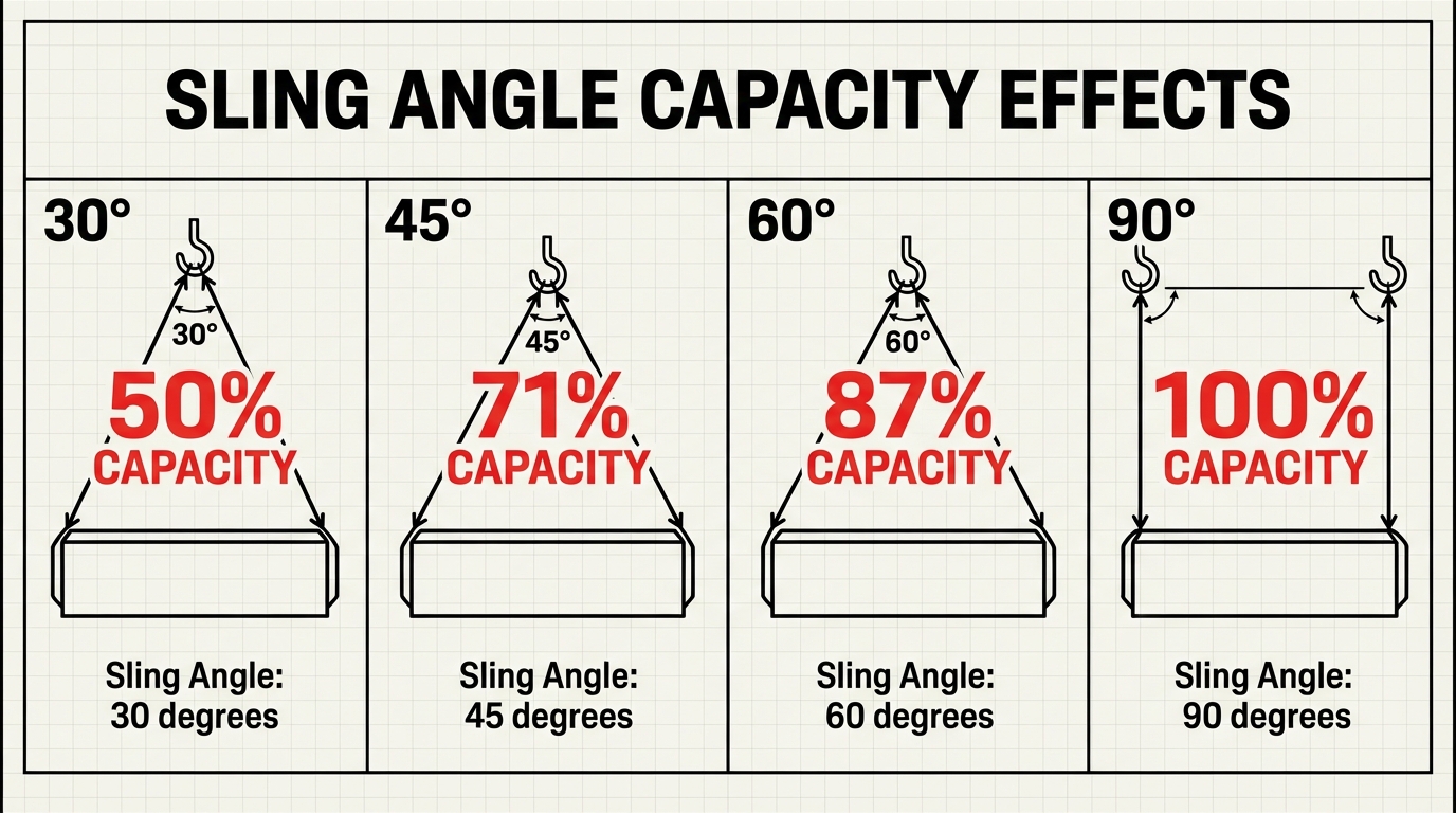
How Do 30-Degree Sling Angles Affect Rated Capacity?
30-degree sling angles affect rated capacity by cutting it in half. According to Lift-All’s sling angle effect chart, a 30-degree angle from horizontal reduces a sling’s capacity to 50% of its vertical rating, with a tension multiplier of 2.000 on each leg. This means each sling leg carries twice its normal load. Because of this severe capacity reduction, most rigging professionals treat 30 degrees as the absolute minimum allowable angle for spreader bar operations. Operating at or near this threshold leaves almost no safety margin, making it a configuration best avoided whenever lift geometry permits a steeper angle.
How Do 45-Degree Sling Angles Affect Rated Capacity?
45-degree sling angles affect rated capacity by reducing it to approximately 70.7% of the sling’s vertical rating. The tension multiplier at this angle is 1.414, meaning each sling leg experiences roughly 41% more force than it would in a straight vertical pull. According to US Cargo Control’s sling angle calculations, this reduction follows a direct trigonometric relationship based on the sine of the angle. While 45 degrees is commonly encountered in field rigging, it still represents a significant capacity loss. Riggers selecting spreader bars for rental should verify that the bar’s load chart accounts for this reduced rating before committing to the configuration.
How Do 60-Degree Sling Angles Affect Rated Capacity?
60-degree sling angles affect rated capacity by reducing it to 86.6% of the sling’s vertical rating. According to Ashley Sling’s angle calculation guide, this angle requires a tension multiplier of 1.155 per sling leg. Compared to shallower configurations, the 60-degree angle preserves a much larger share of the sling’s original capacity. For this reason, 60 degrees is widely regarded as the preferred minimum sling angle in professional rigging practice. When renting a spreader bar, selecting a span that keeps sling angles at or above 60 degrees provides a practical balance between headroom requirements and load-carrying efficiency.
How Do 90-Degree Sling Angles Affect Rated Capacity?
90-degree sling angles affect rated capacity by preserving 100% of the sling’s vertical rating. At a true vertical orientation, the tension multiplier is 1.000, so each sling leg carries only its proportional share of the load with no additional force from angular loading. Although this configuration delivers maximum capacity, achieving a perfect 90-degree angle is rarely practical with spreader bars because it would require sling attachment points directly above and below the crane hook. Understanding this theoretical baseline, however, helps riggers calculate exactly how much capacity each degree of deviation costs during lift planning.
What Does the Term Headroom Mean When Selecting a Lifting Beam?
The term headroom, when selecting a lifting beam, means the vertical distance required between the crane hook and the top of the load. This measurement determines whether a lift can be completed safely within the available overhead space. Understanding headroom affects equipment selection, sling configuration, and overall lift feasibility.
According to Safe and Secure KSA, headroom for a lifting beam is calculated as the sum of the height of the lifting bar and the height of the load attachment point. Lifting beams typically require less headroom than spreader bars because they connect directly to the crane hook through a single top attachment point, eliminating the triangular sling configuration above the beam.
When overhead clearance is tight, such as inside buildings, under bridges, or between structural steel, insufficient headroom can make an otherwise suitable beam unusable. As described by LGH, total minimum headroom for a multi-beam crane lift can be calculated using the Pythagorean Theorem (a² = c² – b²), where “a” is the vertical headroom consumed, “c” is the sling length, and “b” is half the beam span.
Several factors influence how much headroom a lift requires:
- Beam depth and overall height of the lifting device itself.
- Sling length and angle between the beam and load attachment points.
- Shackle and rigging hardware stacked between the crane hook and beam.
- Load height from its attachment points to its uppermost surface.
For projects with limited overhead clearance, basket hitch lifting beams offer a practical solution. These beams minimize vertical space consumption by using slings in a basket configuration with low-profile attachment points. Failing to account for headroom during the planning stage is one of the most common oversights in lift engineering, often forcing last-minute equipment changes that delay projects and increase costs. Confirming headroom early in a lift plan ensures the right beam and rigging reach the job site ready to work.
What Is a Lift Plan and Why Is One Required for Beam Rentals?
A lift plan is a documented procedure that outlines every detail of a crane or rigging operation before the load leaves the ground. Lift plans are required for beam rentals because they verify that the selected spreader bar or lifting beam matches the load weight, rigging configuration, and site conditions.
ASME P30.1 defines three primary categories for load handling activities: Standard, Critical, and Non-Standard. Each category determines the level of planning documentation required to demonstrate compliance with OSHA and ASME standards. Critical lifts, which often involve rented below-the-hook devices like spreader beams, demand the most detailed planning because the consequences of failure are severe.
A thorough lift plan for a beam rental typically addresses:
- Load weight, center of gravity, and dimensions
- Spreader bar or lifting beam type, rated capacity, and WLL
- Sling configuration, sling angles, and resulting load multipliers
- Required headroom clearance based on beam span and sling geometry
- Rigging hardware specifications, including shackle types and sizes
- Crane capacity at the planned working radius
- Site hazards such as power lines, uneven ground, or overhead obstructions
According to a ScienceDirect study on lifting operation safety, human error accounts for approximately 39.3% of incidents, while mechanical failure causes roughly 21.4% of accidental events. A properly executed lift plan directly mitigates both categories by forcing teams to calculate loads, verify equipment ratings, and identify hazards before work begins.
For rental equipment specifically, the lift plan serves a dual purpose. It confirms that the rented beam’s rated capacity and configuration suit the job, and it provides the documentation trail that OSHA inspectors and site safety managers require. Without a lift plan, even properly rated equipment can be misapplied through incorrect sling angles or inadequate headroom calculations. Understanding pickup points and attachment configurations further refines how each lift plan addresses load connection.
What Are Pickup Points and Attachment Points on Lifting Equipment?
Pickup points and attachment points are the designated connection locations on spreader bars and lifting beams where slings, shackles, or hooks interface with the equipment. Understanding how each functions prevents rigging errors and load instability.
Pickup points are the locations on the underside of a spreader bar or lifting beam where the load connects. These engineered connection points, often consisting of pad eyes, clevis pins, or shackle holes, transfer the weight of the load into the beam structure. On adjustable lifting beams, pickup points may reposition in fixed increments along the beam’s length, allowing riggers to match the load’s center of gravity. Proper alignment of pickup points directly beneath the load’s lifting lugs ensures vertical force transfer and prevents side-loading on the hardware.
Attachment points are the locations on the top side of the equipment where it connects to the crane hook or hoist. A lifting beam typically features a single, centered top attachment point that connects directly to the crane hook. Spreader bars, by contrast, use two top attachment points at each end; slings run from these points upward to the crane hook in a triangular configuration. The geometry of these upper attachment points determines the sling angle, which in turn affects both headroom requirements and load distribution across each sling leg.
Misidentifying pickup points and attachment points during rigging setup is a common source of error. According to a 2024 study published in ScienceDirect, human error accounts for approximately 39.3% of incidents in lifting operations. Every connection point on below-the-hook lifting devices must be rated, marked, and inspected before each lift to comply with ASME B30.20 requirements. For rental equipment, verifying that all pickup and attachment points match the lift plan specifications is essential before the load leaves the ground.
With connection points clearly identified, understanding center of gravity ensures those points are positioned correctly for balanced lifts.
What Does Center of Gravity Mean in Spreader Bar and Beam Lifts?
Center of gravity in spreader bar and beam lifts is the single point where the entire weight of a load acts as if it were concentrated. Accurate identification of this point determines rigging attachment placement, load stability, and overall lift safety.
The center of gravity (CG) dictates how a spreader bar or lifting beam must be rigged. When the crane hook aligns directly above the load’s CG, the load hangs level and stable. If the hook position and the CG are misaligned, the load tilts, creating uneven sling tensions that can overload one leg of the rigging while under-loading the other. This imbalance reduces effective rated capacity and introduces a tipping hazard.
For symmetrical loads with uniform density, the CG sits at the geometric center. Asymmetric or irregularly shaped loads shift the CG toward the heavier concentration of mass. Riggers must calculate or physically verify CG location before every lift. Adjustable lifting beams allow pickup points to shift along the beam in precise increments, enabling the rigging crew to position attachment points relative to the actual CG rather than assuming a centered position.
A review of lifting operation incidents published in ScienceDirect found that human error accounts for approximately 39.3% of accidental events, with misjudging load characteristics, including CG location, being a contributing factor. Proper CG identification is not optional; it is a foundational step in any lift plan.
For practitioners working with rental spreader bars and lifting beams, always request documented weight distribution data from the load manufacturer when available. Relying on visual estimates for CG placement is one of the most common yet preventable errors in rigging. Understanding how shackles and rigging hardware connect to these attachment points adds another layer of lift security.
What Are Shackles and Rigging Hardware Terms in Below-the-Hook Equipment?
Shackles and rigging hardware terms in below-the-hook equipment refer to the connection components and associated terminology that link loads to lifting devices such as spreader bars and lifting beams. The most critical hardware types include bow shackles, D-shackles, eye bolts, and swivel hoist rings.
Bow shackles, also known as anchor shackles, have a larger, round “O” shaped body that handles multi-dimensional loading and angled lifts more effectively than narrower alternatives. This wider geometry allows slings to rotate and shift within the bow without concentrating stress on a single point, making them the preferred choice for multi-leg rigging configurations commonly used with spreader bars.
D-shackles, or chain shackles, feature a narrower U-shaped loop designed primarily for straight-line, in-line tension applications. According to Connect-KNKT, using D-shackles at an angle can lead to deformation, which is why proper shackle selection matters when configuring below-the-hook assemblies.
Additional rigging hardware terms encountered in rental include:
- Eye bolts are threaded fasteners with a looped head used to create a direct attachment point on a load.
- Swivel hoist rings are pivot-mounted connection points that rotate under load, reducing sling twist and side-loading risk.
- Turnbuckles are adjustable tensioning devices used to fine-tune sling or wire rope length during rigging setup.
- Master links are oversized alloy links that gather multiple sling legs into a single crane hook connection.
All of these components must comply with ASME B30.26, which governs the marking, inspection, and maintenance of rigging hardware. Every shackle and fitting used in a lift should display its Working Load Limit and be inspected for wear, deformation, or corrosion before each use.
For rental operations specifically, verifying that each piece of rigging hardware carries current documentation and legible WLL markings is one of the simplest yet most overlooked safety steps. Understanding these terms before coordinating a rental ensures the right connectors are specified for the job from the start.
What OSHA and ASME Standards Apply to Spreader Bar and Lifting Beam Rental?
The OSHA and ASME standards that apply to spreader bar and lifting beam rental include OSHA 29 CFR 1926.251, ASME BTH-1, ASME B30.20, and ASME B30.26. These regulations govern design, proof testing, marking, inspection, and safe use of below-the-hook lifting devices.
OSHA 29 CFR 1926.251(a)(4) mandates that special custom-designed lifting accessories for material handling shall be marked to indicate safe working loads and shall be proof-tested prior to use to 125 percent of their rated load, according to the Occupational Safety and Health Administration. This federal regulation applies to every rental spreader bar and lifting beam used on construction sites.
ASME BTH-1 establishes the engineering design criteria for below-the-hook lifting devices, including spreader bars and lifting beams. This standard defines design categories, structural calculations, and fatigue life classifications that manufacturers must follow during fabrication.
ASME B30.20 covers the marking, operation, inspection, and maintenance of below-the-hook lifting devices after they enter service. Rental equipment must comply with its frequent and periodic inspection schedules to remain in safe working condition.
ASME B30.26 governs rigging hardware, including shackles, eye bolts, and swivel hoist rings, covering marking requirements, inspection intervals, and maintenance protocols for these components.
The consequences of non-compliance are severe. A review of 249 overhead crane incidents found 838 OSHA violations, resulting in 133 fatalities, with 37% of cases involving a dropped load, according to OSHA Outreach Courses. For any rental, verifying that equipment meets all four standards before it leaves the yard is the single most important step a project team can take.
What Does Below-the-Hook Lifting Device Mean?
A below-the-hook lifting device is any piece of equipment that attaches between a crane hook and the load being lifted. This category includes spreader bars, lifting beams, vacuum lifters, and magnets.
According to the American National Standards Institute, ASME B30.20-2025 defines below-the-hook lifting devices, commonly referred to as lifters, as equipment that attaches a load to a hoist and includes structural and mechanical lifting devices, vacuum lifters, and magnets. These devices must be designed per ASME BTH-1 and manufactured and used per ASME B30.20 requirements.
Common below-the-hook lifting devices include:
- Spreader bars that convert crane loads into compressive forces
- Lifting beams that carry bending stress from suspended loads
- Vacuum lifters for smooth, non-porous materials
- Magnetic lifters for ferrous steel plates and shapes
Because every component below the hook directly bears the weight of the lifted load, each device carries its own rated capacity, inspection schedule, and proof testing requirement. Understanding this term matters for rental because ASME B30.20 compliance obligations transfer to whoever operates the equipment on site, not just the owner.
With below-the-hook devices defined, inspection requirements for rented equipment determine how compliance is maintained throughout a project.
What Inspection Requirements Apply to Rented Spreader Bars and Lifting Beams?
The inspection requirements that apply to rented spreader bars and lifting beams include proof testing, frequent visual checks, and periodic documented inspections as defined by ASME B30.20. These requirements vary based on service severity and equipment history.
Rented below-the-hook lifting devices must meet the same inspection standards as owned equipment. All new, altered, modified, or repaired lifting devices shall be proof-tested to a minimum of 125% of the rated load prior to initial use, with a written report maintained. According to Tandemloc, Inc., this proof test requirement applies before any device enters service, making it especially relevant for rental equipment that changes hands frequently.
ASME B30.20 establishes frequent inspection intervals based on service conditions:
- Normal service requires monthly inspections.
- Heavy service requires weekly to monthly inspections.
- Severe service requires daily to weekly inspections.
Periodic inspections carry longer intervals but demand greater documentation. For normal and heavy service, periodic inspections must occur at least annually. Severe service environments require quarterly periodic inspections, and records of the most recent periodic inspection must be maintained on file.
When renting spreader bars or lifting beams, the rental provider typically handles proof testing and periodic inspections before delivery. However, the end user remains responsible for frequent inspections throughout the rental period. This shared responsibility is often misunderstood; confirming which inspections have been completed, and which fall to the jobsite team, should be part of every rental agreement conversation.
Understanding these layered inspection obligations helps prevent the mechanical failures that contribute to lifting incidents. With inspection protocols established, the next consideration is how design factors relate to overall equipment safety.
What Is a Design Factor and How Does It Relate to Safety Factor?
A design factor is a multiplier applied during the engineering of a lifting device to ensure its structural members can withstand loads beyond the rated capacity. The subsections below explain how ASME BTH-1 defines design categories and how design factor connects to safety factor.
How ASME BTH-1 Defines Design Categories
ASME BTH-1 defines design categories based on how well the operating environment and load conditions are understood. Design Category A applies where the magnitude and variation of loads are accurately known and the environment is predictable, which allows a lower design factor. Design Category B applies to environments where load conditions are not accurately known or are severe. According to the ANSI Blog’s coverage of ASME BTH-1-2023, Category B lifting devices typically employ a design factor of 3:1. Selecting the correct category is essential because it determines how much built-in structural reserve an engineer must incorporate into every load-bearing component.
How Design Factor Differs From Safety Factor
Design factor differs from safety factor in scope and application. A design factor is the engineering multiplier chosen before fabrication, built into the structural calculations of a lifting device. A safety factor, by contrast, describes the actual margin between the device’s ultimate breaking strength and its rated working load after manufacturing. Both values express a ratio of ultimate strength to working load, yet design factor is a forward-looking engineering input while safety factor reflects the finished product’s real-world capability. In practice, rental customers should confirm that their selected spreader bar or lifting beam meets the ASME BTH-1 design category appropriate for their lift conditions, since an undersized design factor can compromise the entire operation.
Understanding design factor requirements helps ensure the right equipment selection for each project’s complexity.
How Should You Choose the Right Spreader Bar or Lifting Beam Rental for Your Project?
You should choose the right spreader bar or lifting beam rental by matching equipment type, rated capacity, and dimensions to your specific load weight, geometry, and site conditions. The following sections cover how Tway Lifting can support your project and the key rental terms to remember.
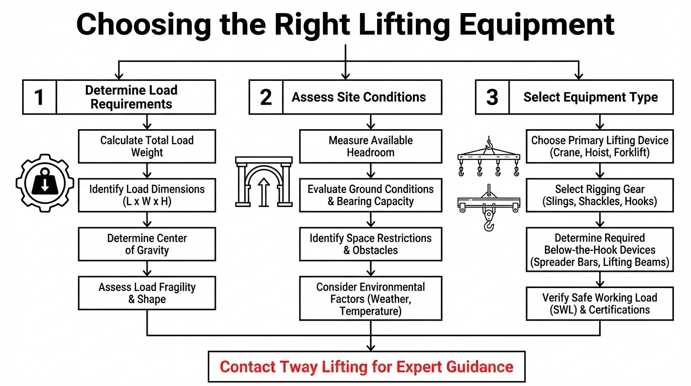
Can Tway Lifting’s Equipment Rental and Custom Fabrication Services Help With Your Lift?
Yes, Tway Lifting’s equipment rental and custom fabrication services can help with your lift. With over 75 years of experience as a rigging manufacturer and distributor, Tway Lifting offers spreader beams rated from 2 to 100 tons with lengths up to 40 feet, along with shackles, hoists, load cells, and telescopic adjustable length bars. Rentals are available on daily, weekly, or monthly terms with free local delivery and pickup.
When a standard rental does not fit the job, Tway Lifting provides custom fabrication of wire rope slings and special lifting assemblies. Every piece of equipment undergoes inspection by certified, factory-trained specialists who verify compliance with OSHA and ASME standards. For projects requiring rapid turnaround, same-day wire rope sling fabrication and emergency service keep operations on schedule.
What Are the Key Takeaways About Spreader Bar and Lifting Beam Rental Terms We Covered?
The key takeaways about spreader bar and lifting beam rental terms covered in this article are the foundational concepts every rigger and project manager should confirm before signing a rental agreement:
- Spreader bars carry compressive loads and require more headroom, while lifting beams carry bending loads with a single top attachment point.
- Rated capacity and Working Load Limit define the absolute maximum a device can safely handle under specified conditions.
- Proof load testing to 125% of rated load is mandatory for all new, altered, or repaired below-the-hook devices before use.
- Sling angles directly reduce capacity; a 30-degree angle from horizontal cuts effective capacity in half.
- Headroom calculations must account for beam height, sling length, and rigging configuration before equipment selection.
- ASME BTH-1, ASME B30.20, and OSHA 29 CFR 1926.251 govern design, manufacture, inspection, and use of all below-the-hook lifting devices.
- Inspection frequency depends on service severity, ranging from daily checks for severe service to annual periodic inspections for normal use.
Understanding these terms ensures safer lifts, smoother rental coordination, and full regulatory compliance on every project.