






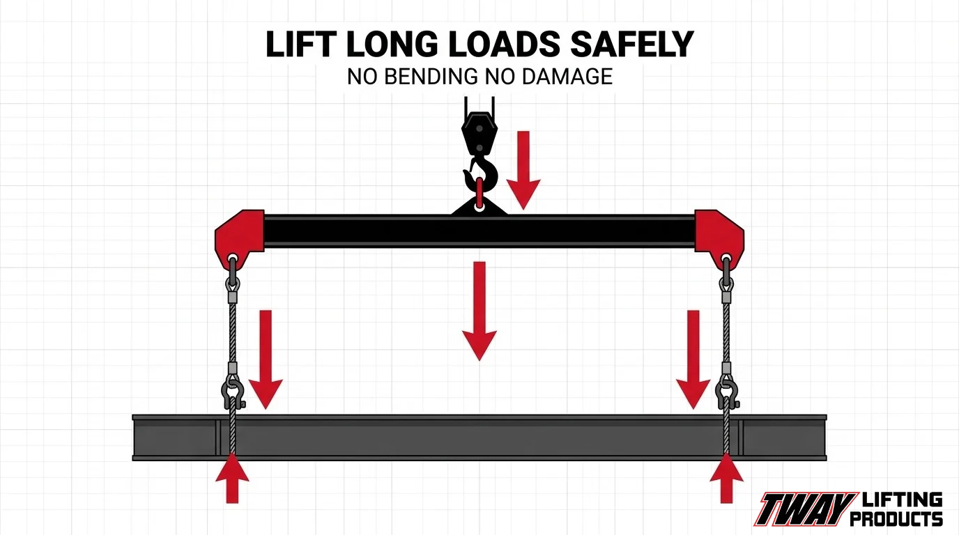

A spreader bar is a below-the-hook lifting device positioned between the crane hook and the load, distributing lift forces across multiple attachment points to prevent the structural damage that concentrated or angled slings cause on long loads.
This guide covers how spreader bars work and how they compare to lifting beams, why long loads are inherently vulnerable to bending and compression during a lift, how vertical sling geometry eliminates the inward forces that damage load structure, which load types require a spreader bar and which bar type fits each application, how bars are sized and rigged for specific loads, and what inspection standards and regulations govern their use.
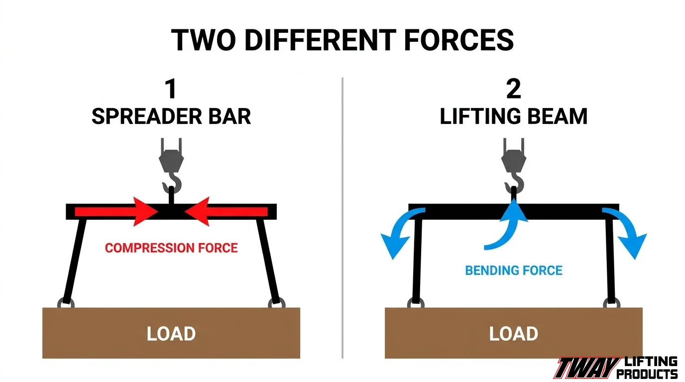
A spreader bar converts inward-angled sling legs into near-vertical ones, removing the horizontal compression that causes bending stress, buckling, and deformation in steel beams, pipes, panels, and machinery frames. The difference between a spreader bar and a lifting beam is structural: a spreader bar acts as a compression member, while a lifting beam acts primarily as a bending member attached at its center to the crane hook.
Long loads are vulnerable because end-point lifts maximize mid-span bending moment, and hollow or thin-walled sections can lose 10% to 20% of their buckling capacity from compressive deformation alone. Spreader bars address this by pushing attachment points outward so slings hang plumb, reducing sling tension to its minimum possible value at each leg.
Sizing, rigging configuration, and compliance with OSHA 29 CFR 1926.251, ASME B30.20, and ASME BTH-1 determine whether that protection holds from hook to set-down.
What Is a Spreader Bar and How Does It Work in a Lift?
A spreader bar is a below-the-hook lifting device that connects to a crane hook above and distributes load weight across multiple attachment points below. The following sections cover how spreader bars distribute forces, how they differ from lifting beams, and how their geometry changes the rigging equation.
How Does a Spreader Bar Distribute Load Forces Across a Long Object?
A spreader bar distributes the load across more than one point, thereby increasing stability during lifting. According to the Federal Mine Safety and Health Review Commission, a spreader bar is positioned below the hook of a crane, with slings running from its ends down to the load, spreading attachment points laterally across the object’s length.
For four-point lifts, the Bureau of Ocean Energy Management notes that static forces are assumed to distribute 75% to one pair of diagonally opposed slings and 25% to the other pair, with all slings and accessories selected for maximum loads. This uneven distribution makes proper sling and hardware selection critical, not optional. Matching each component to the worst-case load scenario is what prevents failure mid-lift.
What Is the Difference Between a Spreader Bar and a Lifting Beam?
The difference between a spreader bar and a lifting beam is in how each device handles structural forces. According to the Federal Highway Administration, spreader beams are designed as compression members, with minor bending from self-weight and sling eccentricity. Lifting beams, by contrast, are primarily bending members that attach at their center directly to the crane hook, suspending the load from each end.
The Naval Postgraduate School defines a spreader as a beam or bar that holds apart two or more lifting slings suspending a load with two or more attachments. MIOSHA’s crane safety training reinforces this distinction practically: a truss, for example, must be lifted with a spreader beam rather than a single hook, precisely because a single-point lift cannot safely manage load geometry across a wide span.
How Does Rigging Geometry Change When a Spreader Bar Is Used?
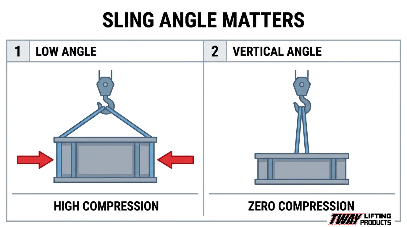
Rigging geometry changes when a spreader bar is used by converting inward-angled sling legs into near-vertical ones, eliminating the horizontal compression forces that angled slings impose on a load. Without a spreader bar, slings run inward from the crane hook to the load at acute angles, creating horizontal force components that squeeze or bend the load inward along its length.
A spreader bar pushes the sling attachment points outward to match the load’s width or lift points, so slings hang nearly straight down. According to NIOSH, 24 of 40 construction deaths caused by being struck by a load were attributed to rigging failure, underscoring that geometry errors in rigging carry life-threatening consequences. Correct sling geometry, enabled by a properly sized spreader bar, is one of the most controllable variables in preventing those failures.
Why Are Long Loads Especially Vulnerable to Structural Damage During Lifting?
Long loads are especially vulnerable to structural damage during lifting because their geometry concentrates bending stress, compressive forces, and torsional loads at points that may exceed the material’s design capacity. The following sections explain how sling angle, end-point attachment, and material flexibility each contribute to that risk.
Why Does Sling Angle Cause Inward Compression on Long Loads?
Sling angle causes inward compression on long loads because angled sling legs resolve into both a vertical lifting component and a horizontal inward-pushing component. As the angle decreases from vertical, that horizontal force grows, squeezing the load laterally along its length. For rigid steel members this may cause localized buckling; for hollow or thin-walled sections the effect is more severe. Proper rigging plans address this directly: the Hanford Site Hoisting and Rigging Manual requires every lift sketch to document sling angles, attachment methods, and sling tension at the actual configuration used.
How Does Bending Stress Form When a Long Load Is Lifted from End Points?
Bending stress forms when a long load is lifted from end points because the unsupported span between attachment locations carries the full distributed weight of the load as a bending moment. As established by beam mechanics, the moment at any interior point depends on the magnitude and position of each concentrated reaction force, meaning end-point lifts maximize the mid-span moment. A Texas Department of Transportation study on curved steel girders found that four lift points provide better resistance to girder twist than two, and that lifting at the quarter points maximizes buckling capacity. Moving attachment points inward from the ends directly reduces peak bending stress and improves stability. For long fabricated members, this geometry difference between a two-point and four-point configuration is not a minor refinement; it is frequently the deciding factor between a successful lift and a permanently deformed structural member.
Why Are Flexible or Hollow Long Loads at Greater Risk of Deformation?
Flexible or hollow long loads are at greater risk of deformation because their cross-sections offer less resistance to the combined bending and compressive forces generated during a lift. NASA research on thin-walled cylinders found that prebuckling deformations in unstiffened isotropic cylinders under compression can reduce buckling capacity by 10% to 20%, meaning the load may fail well below its theoretical limit when any initial geometric imperfection is present. Flexible members such as unsupported trusses or thin-gauge panels deflect under their own weight between attachment points, introducing secondary bending that compounds the primary lift-induced stress. Hollow tubular sections face similar vulnerability at the sling contact zones, where concentrated bearing loads can locally collapse the wall.
How Does a Spreader Bar Eliminate Harmful Sling Angles?
A spreader bar eliminates harmful sling angles by holding sling attachment points apart, forcing sling legs to hang vertically rather than converging inward at an acute angle. The following sections explain how vertical sling legs change the force profile on a load and what happens to compression forces when sling angles reach ninety degrees.
How Do Vertical Sling Legs Change the Force Profile on a Long Load?
Vertical sling legs change the force profile on a long load by removing the inward horizontal component that low-angle slings generate. According to the U.S. Department of Energy, low sling angles apply a larger force due to the load angle factor within the sling itself and also apply a large horizontal force that must be addressed. That horizontal force is what drives inward compression against a load’s sides.
The American Society of Safety Professionals confirms that sling tension per leg equals W / (N · sin θ). At 90 degrees, sin θ equals 1, so each leg carries only its proportional share of the load weight with no force multiplication. At shallower angles, sin θ drops well below 1, driving tension and horizontal compression sharply upward.
What Happens to Compression Forces When Sling Angles Reach Ninety Degrees?
Compression forces on the load effectively reach their minimum when sling angles reach ninety degrees. With legs hanging plumb, all sling tension acts vertically, leaving no horizontal resultant force pressing inward on the load’s attachment points or body. The spreader bar maintains that ninety-degree geometry by physically separating the pickup points to match the load’s width or lift-point spacing, ensuring the sine term in the tension formula stays at its maximum value throughout the lift.
What Types of Loads Most Commonly Require a Spreader Bar?
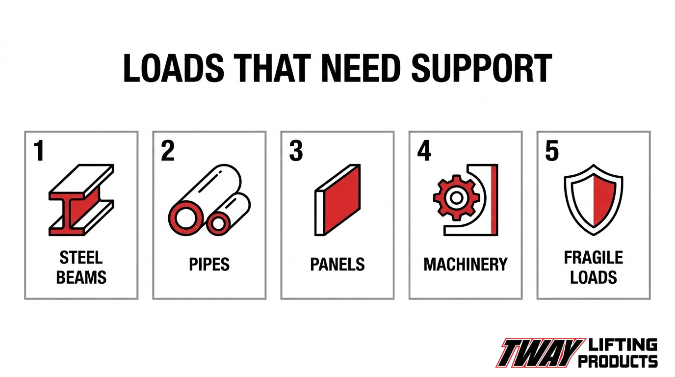
The types of loads most commonly requiring a spreader bar include steel beams, pipes, prefabricated panels, machinery frames, and fragile pre-finished members. Each load type presents distinct deformation risks that vertical sling geometry alone cannot safely address.
When Do Steel Beams and Structural Members Need a Spreader Bar?
Steel beams and structural members need a spreader bar when their length makes single-point or narrow-angle rigging likely to induce bending or lateral buckling. According to the Federal Highway Administration’s Engineering for Structural Stability in Bridge Construction, spreader beams are designed as compression members, while lifting beams act primarily as bending members, making each appropriate for different structural configurations. Long I-beams and girders are especially sensitive to lift-point geometry because even minor eccentricity at sling attachments introduces unintended bending moments. Using a spreader bar establishes controlled attachment spacing, keeping compressive forces within the bar rather than transferring damaging stresses into the beam itself.
When Do Pipes and Tubular Structures Require Spreader Bar Protection?
Pipes and tubular structures require spreader bar protection when their hollow cross-sections make them vulnerable to crushing or ovalization under inward sling forces. A NASA study on thin-walled circular cylinders found that prebuckling deformations in unstiffened cylinders in compression can reduce buckling load by 10 to 20 percent, confirming that even modest compressive loading can initiate failure. Large-diameter steel pipe sections used in arch rib bridge construction, for example, are routinely lifted using coordinated multi-point configurations to prevent this type of deformation.
When Do Prefabricated Panels Require a Spreader Bar During Lifting?
Prefabricated panels require a spreader bar during lifting when their span, weight distribution, or surface rigidity cannot safely tolerate inward sling compression at narrow angles. OSHA 29 CFR § 1926.251(a)(4) specifically addresses this load type, requiring that custom lifting accessories for modular panels and prefabricated structures be marked with safe working loads and proof-tested to 125 percent of rated load prior to use. Additionally, ASME B30.20 governs the marking, construction, inspection, testing, and operation of all below-the-hook lifting devices used in these applications, while BTH-1 addresses design requirements separately. For large panels with distributed mass, a spreader bar creates the attachment geometry needed to lift evenly without edge loading.
When Do Machinery Frames and Industrial Equipment Need a Spreader Bar?
Machinery frames and industrial equipment need a spreader bar when multiple, spread-apart lift points are required to prevent racking, twisting, or point-load stress concentrations. Equipment such as HVAC rooftop units, generator sets, and press frames typically have asymmetric mass distribution and rigid welded structures that cannot flex to accommodate uneven rigging forces. A MIOSHA training scenario explicitly states that trusses must be lifted with a spreader beam rather than a single hook, underscoring that rigid framed assemblies share the same geometry requirements as structural steel. Matching the spreader bar span to the equipment’s lift point spacing keeps sling legs vertical and eliminates lateral loading on the frame.
When Do Fragile or Pre-finished Long Loads Require Spreader Bar Use?
Fragile or pre-finished long loads require spreader bar use when surface contact from angled slings would cause abrasion, denting, or cosmetic damage that compromises either function or appearance. Coated structural members, glazed curtain wall sections, finished architectural steel, and pre-painted panels all fall into this category. A spreader bar keeps sling legs vertical and positions attachment hardware at designated lift points, eliminating the sliding contact that angled slings create along a finished surface. For these loads, spreader bar selection is as much a quality-protection decision as a structural one.
What Types of Spreader Bars Are Available and When Is Each Used?
The types of spreader bars available include fixed-length, adjustable, and modular multi-point systems. Each suits a different combination of load geometry, lift frequency, and attachment-point requirements, covered in the section below.
When Is a Fixed-Length Spreader Bar the Right Choice?
A fixed-length spreader bar is the right choice when a job involves repeatedly lifting loads of identical dimensions, such as standard steel beams, prestressed concrete members, or identically sized HVAC units. Because the span and attachment points never change, a fixed bar can be precisely engineered to its rated load, with no moving parts that could wear or misalign over time. OSHA 29 CFR § 1926.251(a)(2)(i) requires rigging equipment to carry permanently affixed, legible identification markings indicating the recommended safe working load, a standard that fixed bars satisfy straightforwardly since their geometry and WLL are constant. For high-cycle production environments where the same load profile repeats every shift, fixed-length bars offer the most reliable and lowest-maintenance solution.
When Is an Adjustable Spreader Bar Preferred Over a Fixed One?
An adjustable spreader bar is preferred when lift attachment points vary between loads or when a single piece of equipment must serve multiple load widths across a project. Telescoping or pin-adjusted designs allow the rigger to change the span between lifting points without swapping equipment, reducing downtime on sites where load dimensions change frequently.Tway Lifting’s rental inventory includes telescopic adjustable-length spreader bars, covering a wide range of industrial and construction applications. The tradeoff is that each span setting must be verified against the bar’s rated capacity table before the lift, since adjusting span can alter the load distribution and compression forces on the bar itself.
When Is a Modular or Multi-Point Spreader Bar System Needed?
A modular or multi-point spreader bar system is needed when a single-span bar cannot adequately control bending moment, lateral stability, or twist across the full length of a very long or geometrically complex load. According to a Texas Department of Transportation study on curved steel girders, four lift points provide better resistance to girder twist than two, and four lifting reactions reduce the maximum bending moment throughout the span. Modular systems achieve this by linking multiple spreader components into a framework that positions four or more attachment points precisely along the load’s length. They are most common in bridge girder erection, large structural steel assemblies, and industrial equipment installations where load geometry exceeds what a single bar can safely manage.
How Is a Spreader Bar Sized and Rated for a Specific Long Load?
Sizing a spreader bar requires matching three variables: the load’s physical dimensions, its total weight, and the geometry of its attachment points. The following sections cover span selection, working load limit calculation, and how attachment locations drive bar selection.
How Does Load Length Determine the Required Spreader Bar Span?
Load length determines the required spreader bar span by establishing the minimum distance needed between sling attachment points to keep slings vertical and prevent inward compression on the load. The bar span must place lift points far enough apart to clear the load’s width or structural features while maintaining acceptable sling angles. Rigging plans must document the item’s dimensions and center of gravity before span selection, as the Hanford Site Hoisting and Rigging Manual specifies that every rigging-plan sketch must include load dimensions and lift point identification. Under-spanning a bar forces slings inward, reintroducing the same compressive forces the bar is designed to eliminate.
How Does Working Load Limit Get Calculated for a Spreader Bar?
Working load limit (WLL) for a spreader bar is calculated by applying a safety factor to the bar’s ultimate strength, then confirming that figure covers the actual rigged load in the planned configuration. According to the FEMA National Urban Search and Rescue Response System, the allowable working load should not exceed one-fourth of the ultimate strength, establishing a minimum 4:1 design factor. Equipment must carry permanently affixed WLL markings under OSHA 29 CFR 1926.251(a)(2)(i). Justin Boehm of LEEA warns that a recurring failure theme involves equipment that appears to operate well within its rated safe working load, underscoring why conservative WLL calculations and verified markings matter more than the nameplate figure alone.
How Do Attachment Point Locations Affect Spreader Bar Selection?
Attachment point locations affect spreader bar selection by determining whether a two-point or four-point configuration is needed and where along the load the bar’s end connections must land. A Texas Department of Transportation study on curved steel girders found that four lift points provide better resistance to girder twist than two, and that lifting at the quarter points maximizes buckling capacity. For four-point lifts, static forces distribute approximately 75% to one pair of diagonally opposed slings and 25% to the other, requiring all slings and hardware to be selected for the maximum load case. Bars must therefore be specified not just for overall WLL but for the specific horizontal spread that places each connection directly above the designed lift point on the load.
What Rigging Configurations Are Used With Spreader Bars on Long Loads?
Rigging configurations used with spreader bars on long loads fall into two primary categories: two-point and four-point setups. Each configuration suits different load geometries, weight distributions, and structural sensitivity requirements.
How Does a Two-Point Rigging Configuration Protect a Long Load?
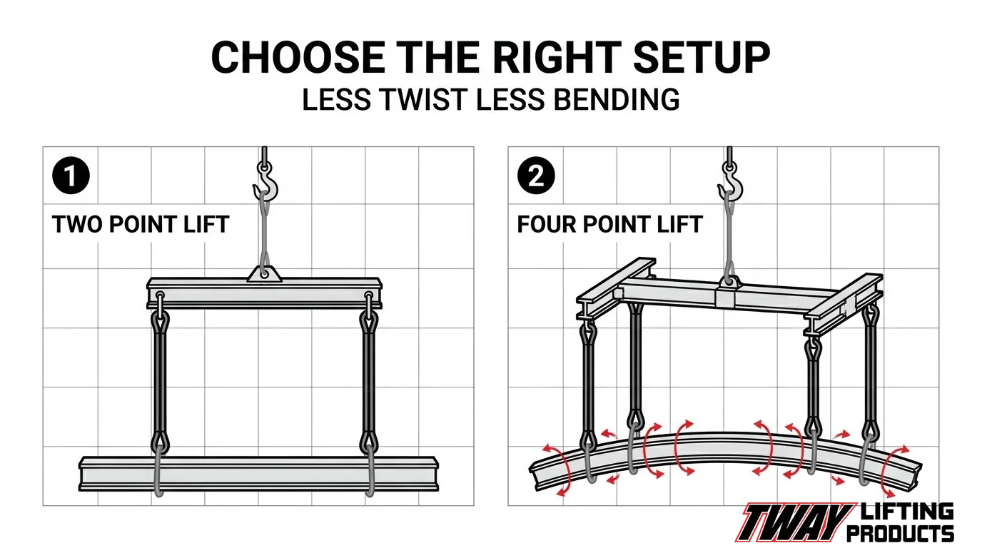
A two-point rigging configuration protects a long load by positioning one sling attachment at each end of the spreader bar, creating two evenly spaced vertical lift points along the load’s length. This spreads the crane’s hook load across two locations rather than concentrating it at one point, reducing peak bending stress in the mid-span of the load. The vertical sling legs that a spreader bar enables eliminate inward horizontal compression forces that angled slings would otherwise impose on the load’s sides. Two-point configurations work well for symmetric, uniform loads such as straight steel beams, pipes, and lumber bundles where the center of gravity sits between the two lift points. For most standard long loads, this setup delivers adequate bending moment reduction with straightforward rigging geometry.
When Is a Four-Point Rigging Configuration With a Spreader Bar Necessary?
A four-point rigging configuration with a spreader bar is necessary when a long load requires both twist resistance and maximum bending moment reduction along its full length. According to a Texas Department of Transportation study on curved steel girders (TxDOT Project 0-5574), four lift points provide better resistance to girder twist compared to two lift points, and four lifting reactions also lead to a reduction in the maximum bending moment. The same research found that lifting at the quarter points maximizes buckling capacity for horizontally curved segments. Four-point configurations are essential for curved structural members, wide prefabricated panels, and any load where a two-point setup would leave unsupported spans vulnerable to deformation. Per 29 CFR § 1926.251(a)(1), all rigging equipment used in these configurations must be inspected before each shift and removed from service if defective. For complex four-point lifts, rigging plans should document sling angles, attachment points, and capacity at each configuration point before the lift begins.
What Are the Inspection and Safety Requirements for Spreader Bars?
The inspection and safety requirements for spreader bars cover three areas: pre-use checks before every lift, specific conditions that remove equipment from service, and the federal and industry standards that govern both.
What Pre-Use Inspection Steps Are Required Before Each Lift?
The pre-use inspection steps required before each lift include examining the spreader bar body for visible deformation, cracks, or corrosion; verifying that all attachment points, pins, and shackles are secure; and confirming that the load rating markings are legible. According to 29 CFR § 1926.251(a)(1), rigging equipment for material handling shall be inspected prior to use on each shift and as necessary during its use to ensure it is safe. Inspectors should also verify that the rated capacity matches or exceeds the planned lift weight before any load is applied.
What Conditions Require a Spreader Bar to Be Taken Out of Service?
The conditions that require a spreader bar to be taken out of service include visible cracks in the bar body, bent or deformed attachment lugs, missing or illegible working load limit markings, corroded or damaged pins, and any weld failures. 29 CFR § 1926.251(a)(1) states that defective rigging equipment shall be removed from service immediately. Illegible capacity markings alone are sufficient cause for removal, since an unmarked bar cannot be safely matched to a load. Equipment that appears intact but lacks documented proof-testing for custom-fabricated designs also fails compliance.
What Standards and Regulations Govern Spreader Bar Use in the US?
The standards and regulations that govern spreader bar use in the US are primarily 29 CFR § 1926.251 (OSHA), ASME B30.20, and ASME BTH-1. OSHA § 1926.251(a)(2)(i) requires permanently affixed, legible identification markings indicating the recommended safe working load. ASME B30.20 covers marking, construction, inspection, testing, maintenance, and operation of below-the-hook lifting devices, while BTH-1 addresses design requirements only. Together, these standards establish a layered compliance framework that any spreader bar operating on a US job site must satisfy.
How Do Custom Fabricated Spreader Bars Address Unusual Long Load Challenges?
Custom fabricated spreader bars address unusual long load challenges by providing engineered geometry, span, and attachment configurations that standard off-the-shelf bars cannot deliver. When a load’s dimensions, weight distribution, or structural sensitivity fall outside catalog specifications, fabrication to exact requirements is the only reliable solution.
Custom fabrication becomes necessary in several situations, including non-standard load lengths, asymmetric center-of-gravity positions, restricted headroom environments, and loads with delicate or pre-finished surfaces requiring specialized lift points. Each scenario demands a bar designed from the ground up rather than adapted from stock inventory.
According to OSHA 29 CFR § 1926.251(a)(4), special custom design lifting accessories for modular panels and prefabricated structures must be marked to indicate safe working loads and proof-tested to 125 percent of their rated load prior to use. This compliance requirement means custom bars must undergo formal load verification, not simply visual inspection, before they enter service.
A rigging plan for a custom lift requires documented inputs: the load’s dimensions and center of gravity, identified lift points, sling attachment methods, sling angles, and confirmed capacity at each configuration point. Without these variables, no custom bar can be safely specified. Custom fabrication also allows engineers to position attachment points precisely to prevent rotation, bending moment accumulation, or lateral instability in loads that standard multi-point configurations would leave unresolved.
For unusually long or asymmetric loads, a purpose-built spreader bar is not a luxury upgrade over standard equipment. It is often the only configuration that keeps sling angles vertical, distributes force correctly, and keeps the load structurally undamaged from hook to set-down.
How Can Tway Lifting’s Custom Fabrication and Rigging Services Support Long Load Lifts?
Tway Lifting supports long load lifts through custom fabrication, rigging equipment rental, and certified specialist expertise. The sections below cover spreader bar sourcing and key article takeaways.
Can Tway Lifting Fabricate or Supply a Spreader Bar Sized for a Specific Long Load?
Yes, Tway Lifting can fabricate or supply a spreader bar sized for a specific long load. Tway Lifting manufactures custom wire rope slings and special lifting assemblies, and rents spreader beams across a wide range of tonnage ratings and spans. Certified, factory-trained rigging specialists can assess load dimensions, center of gravity, and attachment geometry to help determine the right configuration. With over 75 years of rigging manufacturing experience, Tway Lifting matches bar span, working load limit, and hitch configuration to the specific demands of each job.
What Are the Key Takeaways About How Spreader Bars Protect Long Loads from Structural Damage During Lifting?
The key takeaways are that spreader bars eliminate harmful sling angles, control bending stress, and preserve load integrity throughout a lift. According to the FEMA National Urban Search & Rescue Response System, spreader beams act as compression members, while lifting beams function primarily as bending members attached centrally to the crane hook. Choosing the correct device type, sizing it to load span, and verifying working load limits are the three decisions that most directly determine whether a long load arrives undamaged. Proper rigging configuration, inspection before each shift, and compliance with ASME and OSHA standards complete the safety framework every long load lift requires.