








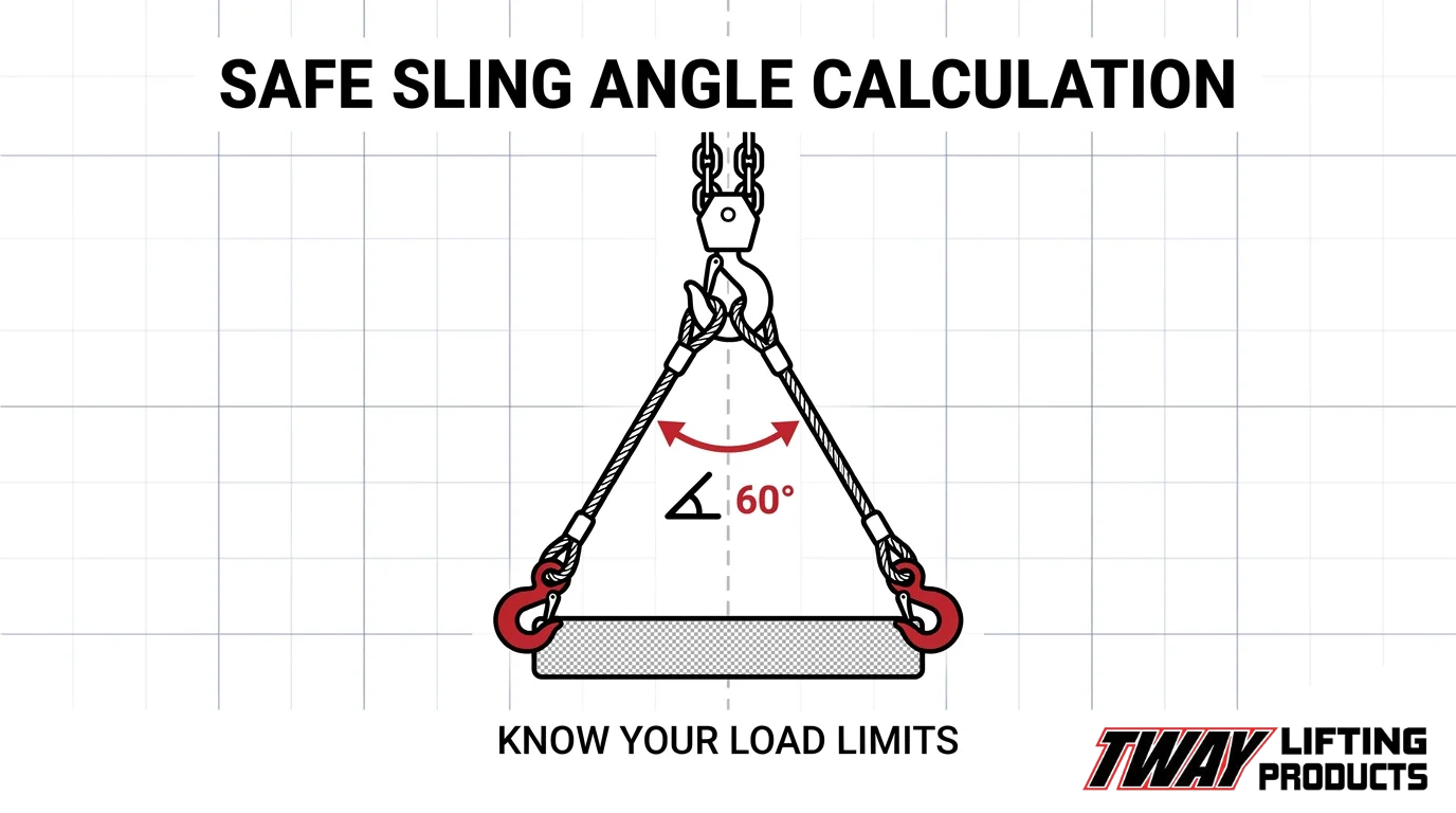

A sling angle is the inclination of a sling leg measured from the horizontal or vertical plane, and it directly determines how much tension each leg carries relative to the total load weight. As that angle decreases from vertical, leg tension rises sharply, often exceeding a sling’s rated working load limit without any change to the load itself.
This guide covers the geometry and formulas behind sling angle calculations, minimum safe angle thresholds, how leg count affects load distribution, applicable OSHA and ASME standards, sling type behavior under angular tension, field tools and reference charts, common rigging mistakes, lift planning requirements, and how certified inspections support safe angle practices.
Sling geometry and calculation form the foundation: we explain how horizontal and vertical reference angles relate, how to apply sling angle factors (1.000 at 90°, rising to 2.000 at 30°), and how to use the formula T = W / (N × sin θ) to determine per-leg tension.
Safe angle thresholds and regulatory requirements establish the working limits: we cover why 30 degrees from horizontal is the practical floor, how WLL reductions are tiered between 30 and 60 degrees from vertical, and when an engineered lift plan becomes mandatory.
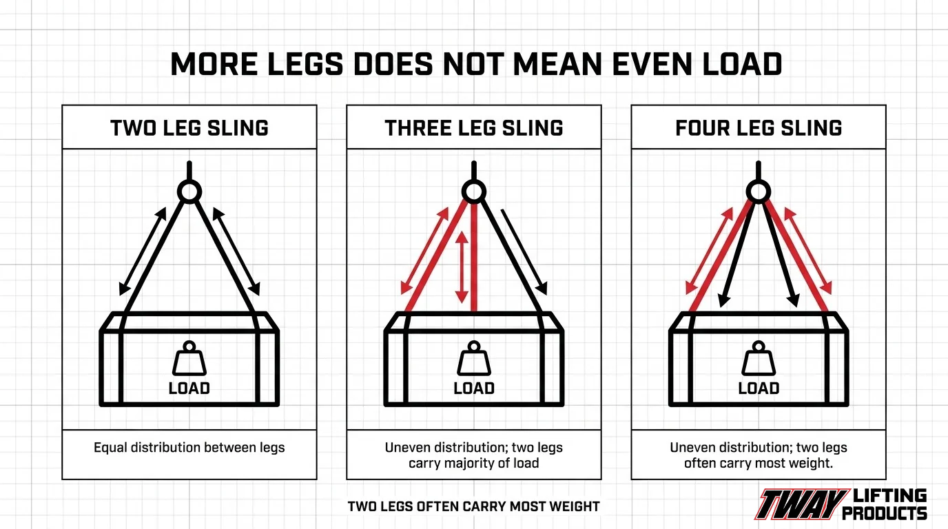
Multi-leg configurations and load distribution address how two-leg, three-leg, and four-leg sling setups change the angle calculation, including why rigid loads can concentrate nearly the full weight on just two legs regardless of leg count.
Sling material, field tools, and lift planning bring the calculations into practice: we examine how wire rope, chain, synthetic web, and round slings each respond to angular tension, how to use calculators and charts on the job, and what compliant lift planning requires from start to finish.
What Is a Sling Angle in Rigging and Lifting?
A sling angle in rigging and lifting is the inclination of a sling leg measured from the horizontal or vertical plane. According to 29 CFR § 1910.184, an angle of five degrees or less from vertical may be treated as a true vertical angle of loading. This section covers how the angle is defined, why geometry changes load forces, and what standards govern angle-based capacity.
How Is a Sling Angle Defined in Rigging?
A sling angle is defined as the measurement between a sling leg and either the horizontal or vertical reference plane during a lift. The angle directly determines how much tension each leg must carry relative to the total load weight. As the angle between the sling legs widens and each leg moves further from vertical, the tension in every leg increases, even if the lifted load remains unchanged. This geometric relationship is the foundation of all sling angle calculations in rigging practice.
What Is the Difference Between a Horizontal and Vertical Sling Angle?
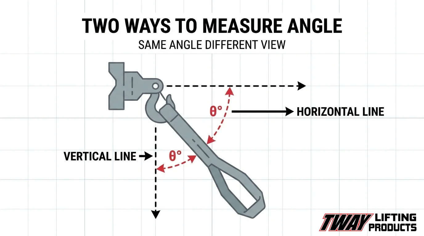
The horizontal sling angle and vertical sling angle describe the same leg position from opposite reference planes; they are complementary angles that always sum to 90 degrees. If a sling leg forms a 30-degree angle from vertical, it simultaneously forms a 60-degree angle from horizontal. Rigging tables and WLL reduction schedules frequently express both values, so riggers must confirm which reference plane a given chart or regulation uses before applying any capacity factor. Confusing the two reference planes is one of the most common and consequential calculation errors in field rigging.
Why Does Sling Geometry Create Increased Tension?
Sling geometry creates increased tension because a non-vertical leg must generate a larger force to produce the same vertical lifting component needed to support the load. The vertical component of each leg’s tension must equal its share of the total load weight, but the actual tension in the leg is always greater than that component whenever the leg is angled. The more acute the angle from vertical, the greater the ratio of actual leg tension to vertical load share. Bernie Winter of LEEA Technical Services explains the practical result: “The angle at which the individual leg makes with the vertical affects the proportion of the load imposed upon it.”
Why Does the Sling Angle Matter for Load Safety?
The sling angle matters for load safety because it directly determines how much tension each sling leg carries relative to the total load weight. As the angle between the sling leg and vertical increases, leg tension rises sharply, often exceeding the sling’s rated capacity without any change in the load itself.
Central to this risk is the relationship between working load limit (WLL), breaking load, and factor of safety. According to the NSW Government Dogging and Rigging Guide, the factor of safety is the ratio of the minimum breaking load to the WLL. A fiber steel wire rope with a safety factor of five, for example, has a WLL equal to one-fifth of its guaranteed breaking strength. When sling angle tension multiplies leg load beyond that WLL, the safety margin erodes rapidly. Riggers who underestimate angle effects are essentially borrowing against that safety factor without realizing it. Treating the WLL as a fixed number without accounting for angle is one of the most consequential errors in lifting operations.
How Do You Calculate the Sling Angle for a Lift?
Calculating the sling angle for a lift requires measuring the angle of each sling leg from horizontal or vertical, then applying that angle to determine how much tension each leg carries relative to the load. The sections below cover how to measure the angle, read tension-to-load ratios, apply the sling angle factor, and understand what happens as the angle decreases.
How Do You Measure the Horizontal Angle of a Sling?
The horizontal angle of a sling is measured from the horizontal plane to the sling leg at the point of attachment. A higher horizontal angle (closer to 90°) means the sling leg runs more vertically, reducing tension on each leg. A lower horizontal angle increases leg tension significantly.
Rated capacity tables express this relationship directly. According to Table H-1 of 29 CFR 1926.251 (U.S. Government Publishing Office), a 1/2-inch alloy steel chain double sling carries 19,500 lb at a 45° horizontal angle but only 11,250 lb at 30°, a reduction of nearly 42% from a 15° angle decrease alone.
To measure the horizontal angle in the field, riggers typically use an inclinometer or protractor against the sling leg before the lift begins.
What Is the Tension-to-Load Ratio at Different Sling Angles?
The tension-to-load ratio at different sling angles is the relationship between the actual force each sling leg carries and the total load weight. As the horizontal angle decreases, leg tension rises above the load weight because each leg must resolve more of the vertical force component.
The ratios follow a predictable pattern:
- 90° (vertical): Leg tension equals half the load in a two-leg sling.
- 60°: Leg tension increases modestly above the vertical baseline.
- 45°: Leg tension reaches approximately 1.414 times the per-leg load at vertical.
- 30°: Leg tension doubles compared to a fully vertical configuration.
This progression is not linear. The steepest increase occurs below 45°, where small angle reductions produce large tension jumps.
How Do You Use a Sling Angle Factor in Your Calculation?
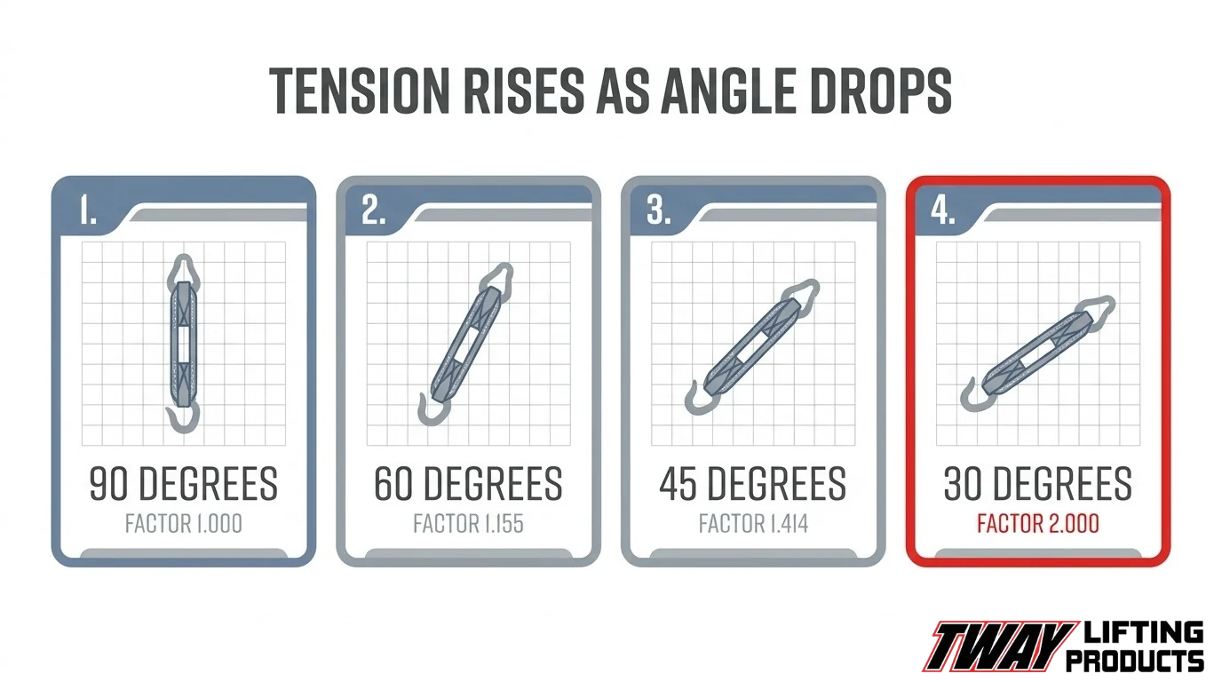
The sling angle factor is a multiplier applied to the per-leg load to determine actual sling leg tension at a given angle. According to the 2018 OSHA Advanced Rigging Principles Student Workbook (OSHA Susan Harwood Grant SH-05018-SH8), the sling angle factors are:
| Horizontal Angle | Sling Angle Factor |
| 90° | 1.000 |
| 60° | 1.155 |
| 45° | 1.414 |
| 30° | 2.000 |
To apply the factor, divide the total load by the number of legs to get the per-leg share, then multiply by the factor for your angle. The result is the actual tension each leg must withstand. That tension must remain below the sling’s rated WLL for the configuration.
Regulatory requirements reinforce this. Under applicable rigging standards, a qualified person or the sling manufacturer must confirm that WLL reductions are maintained whenever a sling operates at any angle from vertical. Sling capacity also depends on material, end fitting type, and attachment method, so the angle factor alone is not sufficient without verifying the full sling rating for the specific configuration.
What Happens to Sling Tension as the Angle Decreases Below 60 Degrees?
Sling tension increases sharply as the angle decreases below 60 degrees. At 45°, the sling angle factor reaches 1.414, meaning each leg carries 41.4% more load than it would in a vertical configuration. At 30°, the factor doubles to 2.000, placing twice the vertical load on every leg.
This acceleration in tension is the core reason shallow sling angles are dangerous. A sling that is correctly rated for a vertical lift can be overloaded simply by widening the spread between attachment points without recalculating for the new angle. Riggers working below 45° should treat every angle change as a new load calculation, not a minor adjustment.
What Is the Minimum Safe Sling Angle for Lifting Operations?
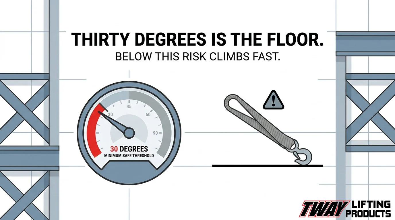
The minimum safe sling angle for lifting operations is generally accepted as 30 degrees from the horizontal. Below this threshold, leg tension increases so dramatically that most slings cannot maintain their rated working load limits safely.
The following sub-sections cover the 30-degree floor, what happens between 30 and 60 degrees, and when angles below 30 degrees require engineered lift plans.
Why Is 30 Degrees Considered the Minimum Sling Angle?
The 30-degree horizontal angle is the practical floor because it corresponds to a sling angle factor of 2.000, meaning each sling leg must carry twice the tension it would bear in a straight vertical lift. At 90 degrees, the factor is 1.000; at 45 degrees, it rises to 1.414; at 30 degrees, it doubles to 2.000, according to the 2018 OSHA Advanced Rigging Principles Student Workbook. That doubling effect consumes virtually all built-in safety margin, leaving no reserve for dynamic forces or load shifts. In practice, riggers who routinely work at 30 degrees are already operating at the edge of safe capacity.
What WLL Reductions Apply Between 30 and 60 Degrees?
WLL reductions between 30 and 60 degrees follow a tiered schedule based on the angle between the sling leg and vertical:
| Angle from Vertical | Permitted WLL |
| Up to 30° | 90% of rated WLL |
| Over 30° up to 45° | 70% of rated WLL |
| Over 45° up to 60° | 50% of rated WLL |
| Over 60° | Not permitted without engineered lift |
These thresholds come from British Columbia’s Occupational Health and Safety Regulation, Part 15, which requires a qualified person or manufacturer to confirm reductions when any angle from vertical is exceeded.
When Does a Sling Angle Require an Engineered Lift Plan?
A sling angle requires an engineered lift plan when the leg angle from vertical exceeds 60 degrees, which corresponds to a horizontal angle below 30 degrees. At that geometry, standard WLL tables no longer apply, and a qualified engineer must calculate actual leg tensions and specify appropriate equipment. Shock loading at any angle is prohibited under the Pacific Northwest National Laboratory Hoisting and Rigging Manual, compounding the risk at shallow angles where tension is already multiplied. Any planned lift approaching these limits should be treated as a critical lift from the outset.
How Does the Number of Sling Legs Change the Angle Calculation?
The number of sling legs changes the angle calculation by altering how tension is distributed across each leg and how the working load limit is derived. The following sub-sections cover the two-leg formula, three- and four-leg approaches, and how uneven loading affects angle across multiple legs.
How Do You Calculate Sling Angle for a Two-Leg Bridle Sling?
The sling angle for a two-leg bridle sling is calculated using the formula: T per sling leg = W / (N × sin θ), where W is the load weight, N is the number of legs, and θ is the loading angle. According to the American Society of Safety Professionals, for an 8,000 lb load with two legs at a 35° loading angle, the tension per leg is 8,000 / (2 × sin 35°) = 6,973.79 lb. This formula applies only when both legs are evenly loaded and rigged with vertical or bridle hitches.
How Do You Calculate Sling Angle for a Three-Leg or Four-Leg Sling?
The sling angle calculation for a three-leg or four-leg sling uses the following formulas:
- 3-leg bridle hitch WLL = WLL (single vertical hitch) × H/L × 3
- 4-leg bridle hitch WLL = WLL (single vertical hitch) × H/L × 4
Here, H is the vertical height and L is the leg length. The H/L ratio is the sine of the loading angle, so a shallower angle directly reduces the rated capacity on every leg. Applying these formulas conservatively is especially important because rigid loads do not guarantee even load sharing across all legs.
How Does an Uneven Load Affect the Angle Across Multiple Legs?
An uneven load causes some legs to carry a disproportionately greater share of the total weight, making the assumed angle calculation unreliable. As Bernie Winter of LEEA Technical Services states: “The angle at which the individual leg makes with the vertical affects the proportion of the load imposed upon it. All legs should therefore be, so far as is practicable, at a similar angle to provide equal loading.” With rigid loads on three- or four-leg hitches, the U.S. Department of Energy warns that two legs can take practically the full load while the remaining legs only provide balance. Matching leg angles as closely as possible is the most practical safeguard against this risk.
What Are the OSHA and ASME Standards for Sling Angles?
The OSHA and ASME standards for sling angles are established primarily through ASME B30.9 and OSHA 29 CFR 1910.184, which together govern how slings must be fabricated, used, inspected, and maintained across lifting operations in the United States.
According to ASME B30.9-2025, the standard covers slings fabricated from alloy steel chain, wire rope, metal mesh, synthetic fiber rope, synthetic webbing, and polyester fiber yarns in a protective cover. It applies to load handling purposes and works in conjunction with other volumes of the B30 Standard, except as restricted in ASME B30.12 and ASME B30.23.
OSHA 29 CFR 1910.184 defines the angle of loading as the inclination of a sling leg measured from the horizontal or vertical plane, with an angle of five degrees or less from vertical treated as a vertical angle of loading. This definition is the regulatory baseline riggers must use when assessing sling leg tension and working load limit reductions.
In practice, these standards do not simply describe safe angles in isolation. They require that any reduction to a sling’s WLL caused by an acute angle be determined by a qualified person or derived from the manufacturer’s specifications. For riggers, this means angle calculations are not optional planning steps; they are a compliance requirement under federal regulation.
How Does Sling Type Affect Angle Calculations and Load Limits?
Sling type directly affects angle calculations and load limits because each material responds differently to angular tension. According to the U.S. Navy Supervisor of Salvage, the weight a sling can safely lift depends on sling material, end fitting type, attachment method, and angular loading combined. The following section cover wire rope, chain, synthetic web, and round sling behaviors.
How Do Wire Rope Slings Respond to Acute Lifting Angles?
Wire rope slings respond to acute lifting angles by experiencing sharply increased leg tension that can exceed their rated capacity. ASME B30.9 governs wire rope sling fabrication, attachment, use, inspection, and maintenance under load-handling conditions. As the angle decreases toward 30 degrees, the load on each wire rope leg can double relative to vertical, so riggers must apply the appropriate sling angle factor and verify the reduced working load limit before the lift proceeds.
How Do Chain Slings Handle Angle-Induced Tension Changes?
Chain slings handle angle-induced tension changes through their rated capacity tables, which list specific working load limits at 30-degree, 45-degree, and 60-degree vertical angles. For a 1/2-inch alloy steel double-leg chain sling, rated capacity drops from 19,500 lb at 60 degrees vertical to just 11,250 lb at 30 degrees vertical, per 29 CFR 1926.251, Table H-1. Chain’s rigid link construction means there is no stretch to redistribute load, making precise angle measurement critical before each lift.
How Do Synthetic Web Slings Behave at Steep or Shallow Angles?
Synthetic web slings behave at steep or shallow angles with reduced margin for error because webbing damage compounds angle-related tension. WorkSafeBC’s OHS Regulation requires removing a synthetic web sling from service when edge cuts exceed web thickness, abrasion penetrates more than 15% of webbing thickness, warp thread damage extends within 1/4 of sling width, or any part is melted, charred, or chemically damaged. Narrow angles concentrate stress on already-vulnerable edges, so pre-use inspection is essential.
How Do Round Slings Compare at Narrow Sling Angles?
Round slings compare favorably at narrow sling angles because their polyester yarn core distributes tension across a circular cross-section, reducing stress concentration. However, the same angular load multiplication applies: at 30 degrees from vertical, leg tension doubles relative to a vertical lift. Round slings still require WLL de-rating at acute angles, and their protective covers must be intact, as hidden core damage cannot be visually confirmed once the cover is compromised.
Understanding how each sling material responds to angle changes helps riggers select the right sling before the load ever leaves the ground.
What Tools or Charts Help Riggers Calculate Sling Angles on the Job?
Riggers use sling angle calculators and sling angle charts to determine safe leg tension and working load limits before and during a lift. The sections below explain how to apply each tool in the field.
How Do You Use a Sling Angle Calculator in the Field?
A sling angle calculator works by applying the formula T = W / (N × sin θ), where W is load weight, N is the number of legs, and θ is the angle of loading from horizontal. Inputting known values gives per-leg tension instantly. According to the American Society of Safety Professionals, a two-leg sling lifting 8,000 lb at 35° produces 6,973.79 lb of tension per leg, well above the naive half-load assumption. Digital calculators, smartphone apps, and pocket reference cards all perform this computation. For site use, the most practical approach is a pre-calculated reference card matched to your specific sling WLL, so tension limits are visible at a glance without manual arithmetic under pressure.
How Do You Read a Sling Angle Chart for Quick Reference?
A sling angle chart is a table that lists the sling angle factor for each standard angle, allowing riggers to adjust rated capacity without trigonometric calculations. The 2018 OSHA Advanced Rigging Principles workbook provides the core reference values: at 90°, the factor is 1.000; at 60°, it rises to 1.155; at 45°, to 1.414; and at 30°, it doubles to 2.000. To use the chart, locate the working angle, read the corresponding factor, and multiply it against the sling’s single-leg WLL to find the required capacity. Posting a laminated chart at the rigging station is one of the simplest ways to prevent under-rated sling selection on fast-moving job sites.
What Are the Most Common Sling Angle Mistakes in Lifting Operations?
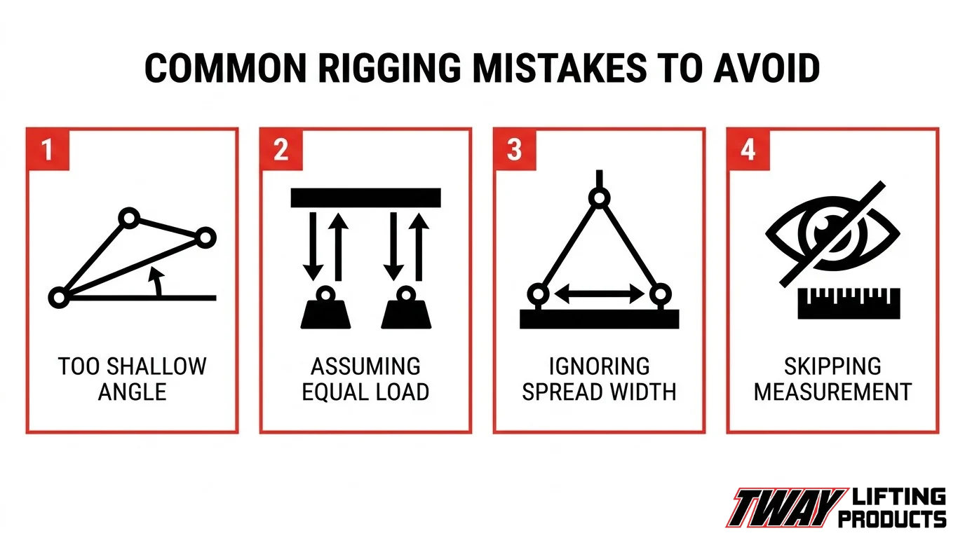
The most common sling angle mistakes in lifting operations include using angles below 30 degrees, ignoring angle-driven WLL reductions, assuming equal load distribution across all legs, and failing to account for horizontal spread when positioning attachment points.
Using Too-Shallow a Sling Angle Without Recalculating WLL
Using a sling angle below 30 degrees without recalculating the WLL is one of the most dangerous errors in rigging. As the angle decreases, leg tension rises sharply. At 30 degrees, the sling angle factor reaches 2.000, meaning each leg carries twice the load it would bear vertically. Riggers who do not apply this multiplier before the lift routinely exceed rated capacity without realizing it.
Assuming All Legs Share the Load Equally
Assuming equal load distribution across three or four sling legs is a well-documented and frequently repeated mistake. According to the U.S. Department of Energy’s Hoisting and Rigging Fundamentals, with a rigid load and more than two sling legs, two legs can absorb nearly the full load while the remaining legs provide only balance. This makes per-leg WLL calculations based on simple leg-count division unreliable and potentially unsafe.
Ignoring the Effect of Attachment Point Spread on Angle
Ignoring attachment point spread when planning a multi-leg lift directly affects the angle each leg forms with the vertical. As attachment points move farther apart horizontally, the sling angle from vertical increases, reducing effective capacity. Riggers who set rigging in the field without measuring this spread often operate at unplanned angles without adjusted load limits. When the spread cannot be reduced, a spreader bar or lifting beam can keep the lower sling legs close to vertical.
Skipping the Angle Measurement Step Entirely
Skipping direct angle measurement is a systematic planning failure. Estimating sling angle by eye introduces enough error to push a borderline lift over capacity. Using a simple plumb line, inclinometer, or on-site sling angle calculator takes under a minute and eliminates this risk. This oversight is especially common on routine or repetitive lifts where crews assume prior setups remain valid under new load conditions.
How Do You Plan a Lift That Accounts for Sling Angle Limitations?
Planning a lift that accounts for sling angle limitations requires identifying angle-of-loading constraints, selecting appropriate rigging configurations, and verifying that all foreseeable risks are addressed before the crane hook is engaged. The sections below cover the regulatory definition of angle of loading, what a compliant lift plan includes, and what real incidents reveal about planning failures.
What Does “Angle of Loading” Mean in a Lift Plan?
The angle of loading is the inclination of a sling leg measured from the horizontal or vertical plane; under 29 CFR § 1910.184, an angle of five degrees or less from the vertical may be treated as a true vertical angle of loading. A bridle wire rope sling, composed of multiple legs gathered into a single fitting over the hook, is the most common configuration where this angle must be calculated and documented before the lift begins. Failing to establish this measurement at the planning stage leaves the rigging team without a defensible load rating for the configuration actually in use.
What Must a Compliant Lift Plan Include?
A compliant lift plan must include a documented sling angle calculation, confirmed working load limits adjusted for that angle, hazard identification, and designation of a qualified planner. According to the Health and Safety Executive, all lifting operations should be planned so they are carried out safely with foreseeable risks taken into account, and the person appointed to plan the operation must have adequate practical and theoretical knowledge and experience of the lifts being undertaken. At minimum, the plan should address:
- Measured sling angle for each leg in the configuration.
- Adjusted WLL based on the angle-of-loading reduction table.
- Load weight verification and center-of-gravity assessment.
- Identification and barricading of the exclusion zone beneath the load.
- Availability and inspection status of all rigging hardware before lift commencement.
What Do Lifting Incidents Reveal About Planning Gaps?
Lifting incidents consistently reveal that planning gaps, not equipment failure alone, are the root cause of fatalities and dropped loads. On November 25, 2008, a 46-year-old rigger died after being struck by a falling load; investigators determined the rigging slings failed due to heat friction, a hazard a thorough pre-lift inspection and plan should have identified. In a separate event on December 6, 2021, a soft sling failed while lifting a coarse coal centrifuge basket at a CHPP facility, dropping the load; the area had not been barricaded and available lifting jigs were not utilized, two controls that belong in any compliant lift plan. These incidents illustrate that sling angle management cannot be separated from broader lift planning discipline.
How Can Certified Rigging Equipment and Inspections Support Safe Sling Angle Practices?
Certified rigging equipment and inspections support safe sling angle practices by ensuring every sling in service meets rated capacity requirements at the angles actually used on the job. The section below addresses Tway Lifting’s inspection capabilities and the key takeaways from this guide.
Can Tway Lifting’s Rigging Inspections Identify Angle-Related Equipment Risks?
Yes, Tway Lifting’s rigging inspections can identify angle-related equipment risks across all major sling types, including wire rope, chain, and synthetic web slings. Tway Lifting’s certified, factory-trained inspection specialists evaluate slings for the physical damage conditions that angle-induced tension accelerates, such as edge cuts, abrasion wear, distorted end fittings, and broken load-bearing stitches. According to WorkSafeBC’s Occupational Health and Safety Regulation, Part 15, a synthetic web sling must be removed from service when edge cuts exceed web thickness, abrasion penetrates more than 15% of webbing thickness, or end fittings are cracked or distorted. These failure modes develop faster when slings operate at steep angles that magnify leg tension. Tway Lifting’s inspection services, which include OSHA-required annual inspections and job site safety inspections, directly target these conditions before they become load failures.
What Are the Key Takeaways About How to Calculate Sling Angles for Safe Lifting Operations?
The key takeaways about how to calculate sling angles for safe lifting operations center on planning, geometry, and equipment integrity. The Health and Safety Executive states that all lifting operations should be planned by a person with adequate practical and theoretical knowledge, with foreseeable risks accounted for in advance. Applied to sling angles, that means:
- Measure the vertical height and horizontal distance before every lift to confirm the actual angle.
- Apply the sling angle factor to the rated WLL: at 60°, multiply by 1.155; at 45°, by 1.414; at 30°, by 2.000.
- Reduce WLL as required when leg-to-vertical angles exceed 30°, and treat angles beyond 60° as engineered lifts only.
- Inspect slings for angle-accelerated wear before and after every use.
- Use certified, properly rated equipment from a trusted supplier to match sling capacity to actual lift geometry.
Safe lifting is ultimately a planning discipline, and knowing your angles is where that planning begins.